
Description
Hard-Numbers: Technical Specifications
- Protection Functions: 50/51 phase/neutral overcurrent, 50N/51N ground fault, 50SG/51SG sensitive ground, 67P/67G directional, 59/27 over/undervoltage, 81U/O frequency, 50BF breaker failure, 79 auto-recloser, 25 synchrocheck
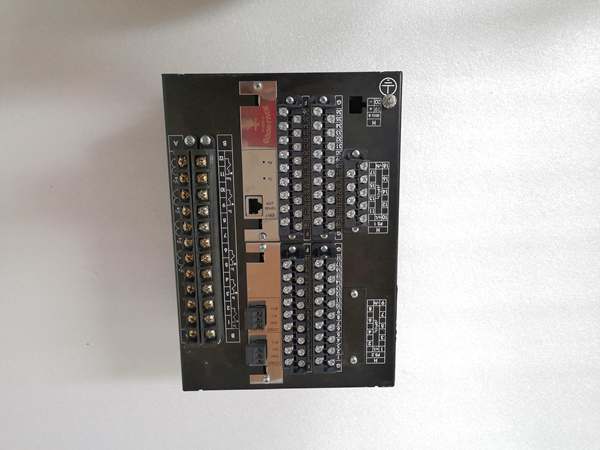
- Slot F I/O: 8 digital inputs + 8 Form-C outputs + 2 trip/close circuit supervision circuits (Option 2 board)
- Slot G I/O: 32 digital inputs (Option 4 board, highest density)
- Total I/O Capacity: 40 digital inputs + 8 digital outputs + 2 supervision circuits
- Communication: Dual redundant 100BaseFX glass fiber (2x ST connectors, 1300nm multimode) + 10/100BaseTX copper Ethernet
- Protocols: IEC 61850 Edition 2 (Protocol 6), Modbus RTU/TCP, DNP 3.0 Level 2, IEC 60870-5-103/104, IEEE 1588 PTP, PRP/HSR
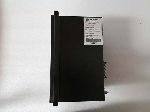
- Power Supply: 110-250V DC (88-300V) / 120-230V AC (96-250V), HI range
- Power Draw: 25-30 VA typical, 45 VA maximum at full load
- Operating Temperature: -40°C to +70°C
- Isolation Rating: 2000V AC RMS I/O-to-chassis
- Dimensions: 168 × 150 × 55 mm (½ 19″ rack, 6U high)
- Weight: 5 kg (11 lbs)
- Fiber Wavelength: 1300nm multimode (62.5/125µm or 50/125µm)

The Real-World Problem It Solves
Salt spray, H₂S, and high EMI kill copper Ethernet and corrode relay guts in coastal refineries and offshore platforms. This unit delivers dual redundant fiber optic ports for EMI immunity and seamless failover, plus conformal coating on all PCBs to survive corrosive atmospheres where standard relays die within 3-5 years.
Where you’ll typically find it:
- Offshore platform substations with salt-spray exposure and high electromagnetic noise from VFDs
- Chemical plant switchgear rooms near H₂S/SO₂ sources requiring extended equipment life
- EHV transmission substations requiring dual-redundant IEC 61850 communication for zero downtime
Bottom line: This is the buy-once-cry-once choice when you need EMI-proof redundancy and can’t afford relay failure in corrosive hellholes.
Hardware Architecture & Under-the-Hood Logic
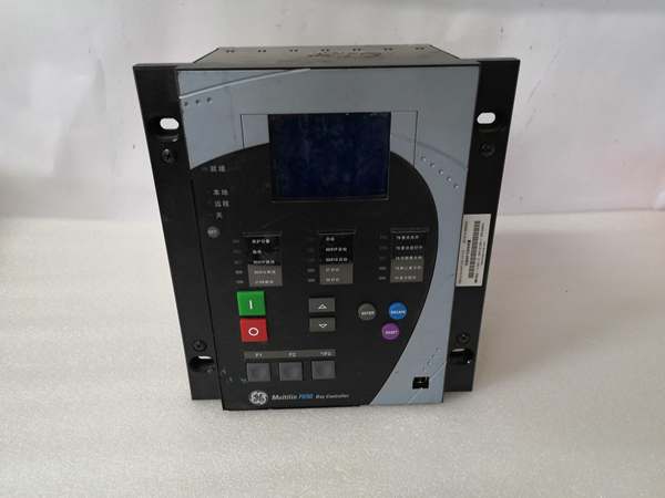
This graphic-display F650 sits on the CAN bus backplane with two independent fiber transceiver modules handling the dual 100BaseFX ports. The Option 4 Slot G board packs 32 digital inputs—the highest density configuration—communicating over CAN at 1Mbps, while the Option 2 Slot F provides supervised trip/close outputs for breaker failure monitoring.
- Main CPU: 32-bit RISC processor (>50 MIPS) runs protection algorithms at 1ms scan cycles, with separate communication processor handling protocol stacks (IEC 61850, DNP, Modbus) to offload the protection core
- DSP Module: Samples all analog inputs at 64 samples per power cycle, feeding filtered I/V data to protection algorithms for sub-cycle fault detection
- Slot F I/O Board (Option 2): 8 programmable digital inputs (24V DC sink/source) + 8 Form-C relay outputs (6A @ 250V AC) + 2 dedicated supervision circuits monitoring trip coil continuity and close coil integrity
- Slot G I/O Board (Option 4): 32 digital inputs in high-density configuration, optically isolated 24V DC inputs, draws up to 320mA when all inputs active—verify your 24V supply can handle the load
- Dual Fiber Transceivers: Two independent 100BaseFX ST port modules operating at 1300nm multimode, each with -14dBm TX power and -31dBm RX sensitivity, managed by dedicated communication processor supporting PRP/HSR protocols
- Conformal Coating: 1-micron thin polymeric film covering all PCB surfaces, protecting against H₂S, SO₂, NO₂, and salt spray; fluorescent dye allows UV inspection for coating integrity
- Power Supply: Switching-mode DC/DC converter with 88-300V DC input range, >80% efficiency, provides isolated 5V, 3.3V, and 24V rails for internal circuits and I/O boards
- IEEE 1588 PTP Module: Hardware-assisted time synchronization over fiber, achieving sub-microsecond accuracy for IEC 61850 GOOSE/SV messaging
PRP sends identical frames over both fiber paths—receiving device discards the duplicate. HSR uses a ring topology with intelligent forwarding. The fiber ports support up to 2km multimode with proper budget calculation. The conformal coating prevents silver whisker growth on SMD components from H₂S exposure, extending MTBF in corrosive environments by 3-5 years compared to uncoated relays.
Field Service Pitfalls: What Rookies Get Wrong
Dual Fiber Path Physical SeparationTechs run both fibers through the same conduit or cable tray, thinking separate switches equal redundancy. One cut conduit kills both paths.
Field Rule: Route fiber paths with physical separation—different cable trays, different conduit runs, different penetrations through walls. If both fibers share a single path, you don’t have redundancy, you have a single point of failure. Document the physical routing in as-built drawings.
Optical Budget IgnoranceJuniors assume fiber works at any distance without calculating loss. They install 3km multimode runs and wonder why link drops intermittently.
Field Rule: Calculate your budget: -14dBm TX – (-31dBm RX) = 17dB total. Subtract 0.5dB per connector (4 connectors = 2dB) plus 0.3dB/km × distance. For 2km multimode: 2dB connectors + 0.6dB fiber = 2.6dB loss, leaving 14.4dB margin—healthy. If margin drops below 3dB, upgrade to single-mode fiber. Test with optical power meter during commissioning.
Conformal Coating Rework DamageWhen replacing components, techs scrape off coating beyond the repair area, exposing nearby traces to corrosion.
Field Rule: Scrape only the immediate repair area using a non-conductive pick. Re-apply compatible conformal coating (same chemistry as original) using a fine brush. Allow full cure time per datasheet—usually 24-72 hours. Inspect under UV light to confirm complete coverage. Document all rework areas.
Slot G Input Current OverloadOption 4’s 32 inputs draw serious current when all active. Techs tap off the same 24V supply powering relays, causing brownouts during fault conditions.
Field Rule: Calculate worst-case input current: 32 inputs × 10mA = 320mA. Supply at least 500mA for margin. Use a dedicated 24V source for digital inputs or size your main supply accordingly. Measure supply voltage with all inputs active—it shouldn’t drop more than 5%. Undervoltage causes erratic behavior you’ll spend weeks chasing.
PRP/HSR Switch Configuration MismatchIT configures both fiber ports in the same VLAN without understanding protocol requirements, causing broadcast storms and latency spikes.
Field Rule: For PRP, put each fiber port on a separate VLAN or use physically separate switches. Enable STP/RSTP on all switches to prevent loops. Configure QoS priority 5-7 for GOOSE traffic. Monitor switch port statistics during commissioning—high packet loss indicates misconfiguration. Test failover by pulling one fiber—SCADA must not blink.
Fiber Connector Contamination in Salt SprayCoastal environments coat ST connectors in salt residue, causing insertion loss. Techs don’t inspect connectors before mating.
Field Rule: Inspect fiber connectors under a microscope or magnifier. Clean with 99% isopropyl alcohol and lint-free wipes every time before mating, even if they look clean. Use connector caps when fibers are disconnected. In salt-spray environments, clean monthly during routine maintenance. A dirty connector eats 3-5dB of your optical budget.
Trip Circuit Supervision MiswiringOption 2’s supervision circuits require series wiring through the trip coil. Techs wire supervision in parallel, defeating the purpose.
Field Rule: Supervision output must be in series with the trip coil. Current flows from supervision output → trip coil → return. Supervision circuit measures this small current (typically 0.5-2mA). If the coil opens, current drops and supervision alarm fires. Test by physically opening the trip coil—alarm should trigger within 100ms. Never rely on supervision you haven’t tested.
Harsh Environment Grounding DegradationIn H₂S environments, ground lugs corrode internally. Techs measure ground resistance but don’t inspect physical connections.
Field Rule: Annual ground lug inspection is mandatory. Remove, clean to bare metal, apply no-oxide grease, torque to spec. Use stainless steel hardware. Measure ground resistance—should be under 5 ohms. In H₂S concentrations over 100ppb, inspect every 6 months. A corroded ground will kill your relay faster than any lightning strike.
Slot G Input Voltage DropLong cable runs to the 32 digital inputs cause voltage drop at the relay. Techs verify at the source but not at the relay terminals.
Field Rule: Measure 24V at the relay terminals with all inputs activated. If it drops below 19.2V (the F650’s minimum), you’ve got voltage drop. Shorten runs, increase wire gauge, or install a local power supply at the cabinet. Voltage-starved inputs cause erratic states that look like field device failures but are actually power issues.
Commercial Availability & Pricing Note
Please note: The listed price is for reference only and is not binding. Final pricing and terms are subject to negotiation based on current market conditions and availability.


