
Description
 Hard-Numbers: Technical Specifications
- Protection Functions: Overcurrent (50/51), Earth Fault (50N/51N), Sensitive Ground Fault (50SG/51SG), Directional Elements (67P/67G), Overvoltage/Undervoltage (59/27), Frequency (81U/O), Breaker Failure (50BF), Auto-Recloser (79), Synchrocheck (25)
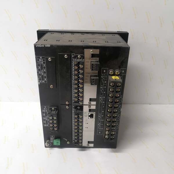
- Slot F I/O: 32 Digital Inputs (Option 4 board)
- Slot G I/O: 16 Digital Inputs + 8 Outputs (Option 1 board)
- Total I/O Capacity: 48 Digital Inputs + 8 Digital Outputs
- Communication: Redundant glass fiber optic serial ports (2 ST connectors) + 10/100BaseTX Ethernet + Front RS232 Port + Basic Display
- Protocols: IEC 61850 Edition 2, Modbus RTU/TCP, DNP 3.0 Level 2, IEC 60870-5-103/104, IEEE 1588 PTP
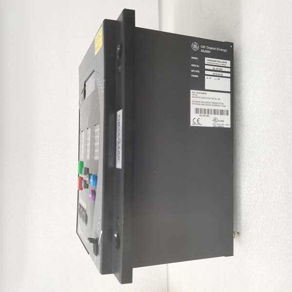
- Power Supply: Redundant HI (110-250V DC / 120-230V AC), dual independent power supplies with automatic switchover
- Power Draw: 25-30 VA typical, 45 VA maximum per power supply
- Operating Temperature: -40°C to +70°C
- Isolation Rating: 2000V AC RMS I/O-to-chassis
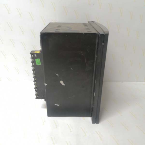
- Dimensions: 168 × 150 × 55 mm (½ 19″ rack, 6U high)
- Weight: 5 kg (11 lbs)
- Language: English/Chinese (basic display model supports dual language)
The Real-World Problem It Solves
Critical substations can’t afford power supply failures, but single power supplies create single points of failure. This unit delivers dual redundant HI power supplies with automatic switchover, glass fiber optic serial communications for EMI immunity, and extensive I/O capacity—eliminating single points of failure in power and communication while maintaining cost-effective serial infrastructure.
Where you’ll typically find it:
- EHV transmission substations with N-1 power redundancy requirements
- Industrial plants with high electromagnetic noise environments
- Critical feeder protection schemes requiring zero power downtime
- Utility substations with strict availability requirements for protection systems
This configuration combines dual power redundancy with EMI-immune fiber communications and high-density I/O, ideal for mission-critical applications where power continuity is paramount.
Hardware Architecture & Under-the-Hood Logic
This is a basic display F650 with redundant power supplies and glass fiber serial communications. The “M” (first) indicates basic alphanumeric display, “M” (second) means no rear serial ports (basic configuration), “D” adds redundant glass fiber optic serial ports, “F” is 10/100BaseTX Ethernet, “1” in Slot F provides 32 digital inputs, “G1” in Slot G provides 16 inputs + 8 outputs, “HI” indicates high-voltage power supply range, “R6” specifies redundant HI power supply, and “E” denotes harsh environment conformal coating.
- Main CPU Board: 32-bit RISC processor (>50 MIPS) with 32MB+ flash memory, executing protection algorithms at 1ms scan cycles
- DSP Module: Handles analog-to-digital conversion at 64 samples per power cycle for current/voltage inputs
- Slot F I/O Board (Option 4): 32 digital inputs (24V DC programmable), communicates via CAN bus
- Slot G I/O Board (Option 1): 16 digital inputs (24V DC programmable) + 8 Form-C relay outputs (6A @ 250V AC), communicates via CAN bus
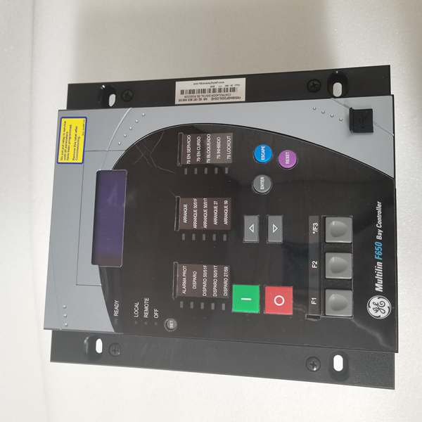
- Basic Display Module: 4×20 character alphanumeric LCD with dual language support (English/Chinese), supports scrolling metering and basic status information
- Redundant Power Supply Module: Two independent HI-range switching power supplies (110-250V DC / 120-230V AC) with automatic failover, rated for high I/O load (up to 45 VA each)
- Communication Module: Dual redundant glass fiber optic serial ports (2 ST connectors, 1300nm multimode) + 10/100BaseTX copper Ethernet
- Harsh Environment Protection: Conformal coating on all PCBs for protection against chemical contaminants and moisture
The redundant power supplies operate in hot-standby mode with automatic switchover. If the primary supply fails, the secondary takes over within milliseconds without interrupting protection functions. Both supplies can operate simultaneously, sharing the load. The glass fiber optic serial ports provide EMI immunity for critical serial communications, using 1300nm multimode fiber with ST connectors. The “E” conformal coating protects against harsh chemical environments, making this unit suitable for coastal, industrial, or other corrosive environments. The basic display provides essential metering and status information in a compact, cost-effective form factor.
Field Service Pitfalls: What Rookies Get Wrong
Redundant Power Supply Testing Errors
Techs test only one power supply at a time and assume redundancy works. Rookies don’t verify automatic failover under load conditions.
Field Rule: Test both power supplies independently first—apply power to Supply 1 only, verify full operation. Disconnect Supply 1, apply power to Supply 2 only, verify full operation. Then apply power to both supplies and simulate a failure by disconnecting Supply 1 while monitoring relay operation—protection must continue uninterrupted. Verify switchover time is less than 50ms. Document power supply health in maintenance records. Never assume redundancy works without testing the actual failover scenario.
Redundant Power Supply Wiring Reversal
Techs wire both power supplies to the same source, defeating redundancy. Or they connect supplies to out-of-phase sources causing ground loops.
Field Rule: Connect each power supply to an independent power source. Measure voltage potential between the two source neutrals—should be less than 5V AC. Use separate circuit breakers for each supply. If independent sources aren’t available, use dual-output UPS or separate feeders from the same substation busbar. Document source assignments clearly. Never parallel power supplies at the source—each must have its own independent feed.
Basic Display Language Configuration
The “M” basic display supports dual language (English/Chinese). Rookies leave it in factory default English when operators need Chinese, or misconfigure language switching.
Field Rule: Configure language in EnerVista under HMI settings. The basic display can scroll between languages on startup. Set primary language to match operator preference. Document language configuration in commissioning package. Test language switching by cycling power—verify display initializes correctly in configured language. Note that basic displays have limited character sets—special characters may not render correctly.
Glass Fiber Connector Polarity Confusion
ST connectors are keyed, but techs sometimes reverse transmit and receive fibers between ports. Rookies create link lights but no actual communication.
Field Rule: Verify fiber polarity before final connection. Use a fiber tester to confirm TX→RX continuity. Standard practice: device TX (red) → device RX (blue). Document polarity in termination records. Glass fiber typically uses 1300nm wavelength—verify fiber type matches. If communication exists on one port but not the other, check for reversed fibers or mismatched wavelength.
Slot F Option 4 High-Density Input Overload
Slot F provides 32 digital inputs—the highest density option. Rookies exceed the board’s input current capability by wiring too many inputs to the same source.
Field Rule: Calculate total input current for Slot F. Each 24V DC input typically draws 5-10mA. With 32 inputs, maximum current is 160-320mA. Verify your external 24V supply can handle this load. Consider grouping inputs and using multiple external supplies if needed. Monitor power supply health under worst-case input activation. Document input current calculations in design documentation.
Harsh Environment Coating Misunderstanding
The “E” conformal coating provides chemical resistance, but techs assume it provides complete environmental protection. Rookies neglect proper sealing and IP rating.
Field Rule: Conformal coating protects PCBs from chemical fumes and moisture but doesn’t replace proper cabinet sealing. Maintain IP52 rating for the relay enclosure. Ensure cabinet gaskets are intact. In corrosive environments, regularly inspect coating integrity—chemical exposure can degrade coating over time. Never scrape or modify coating—this voids protection. Document environment conditions and coating inspection results.
Redundant Power Supply Monitoring Gaps
Techs assume both supplies are healthy because the relay is running. Rookies don’t monitor individual supply health until failure occurs.
Field Rule: Configure alarm outputs for each power supply. Use EnerVista to set up Supply 1 healthy alarm and Supply 2 healthy alarm. Monitor both alarms in SCADA. Set up preventative maintenance alerts—replace supply before failure if trending shows degradation. Document supply health trends. Implement scheduled testing every 6-12 months to verify redundancy. Don’t wait for actual failure to discover a problem.
Basic Display vs. Graphic Display Expectations
Techs expect full HMI graphics from the “M” basic display. The basic alphanumeric display shows metering and status but cannot render single-line diagrams.
Field Rule: Understand display limitations—4×20 characters = 80 characters total, no graphics. Use scrolling mode to display multiple metering values. Configure display cycle time (typically 2-5 seconds per screen) to show critical values. For advanced visualization, use EnerVista Web Server or external HMI. Document which screens show which information. Don’t try to display complex graphics—stick to essential metering and status.
Slot G I/O Board Configuration Confusion
Slot G provides 16 inputs + 8 outputs. Rookies misconfigure the board type in software, treating it as Option 2 (supervision) or Option 4 (32 inputs).
Field Rule: Verify Slot G configuration in EnerVista under Inputs/Outputs > Board G. Set board type to “16 INP + 8 OUT.” Configure input voltage thresholds for each input group. Assign output types (NORMAL/PULSE/LATCH). Test each input and output individually. Document board configuration and wiring assignments. Never assume factory default matches your application—verify all settings.
Glass Fiber Budget Calculation Errors
Rookies don’t calculate optical power budget, assuming glass fiber works over any distance. Excessive loss causes intermittent communication.
Field Rule: Calculate optical budget: transmitter power (typically -14 dBm) minus receiver sensitivity (typically -30 dBm) = 16 dB budget. Subtract connector loss (0.5dB per ST connector × 2 = 1dB) and fiber loss (typically 0.3dB/km for 1300nm multimode). For 2km cable: 1dB connectors + 0.6dB fiber = 1.6dB total loss, leaving 14.4dB margin—acceptable. Test with optical power meter during commissioning. Document optical budget and test results. If margin is less than 3dB, consider shorter cable or lower-loss connectors.
Redundant Power Supply Replacement Without Full Testing
Techs replace a failed power supply and verify the relay works, but don’t test the new supply’s redundancy capability.
Field Rule: After replacing a power supply, perform full redundancy testing. Test the new supply independently (other supply disconnected). Test failover from old supply to new. Test failover from new supply to old. Verify both supplies can handle full load. Document replacement date, model, and test results. Update maintenance records. A replacement power supply isn’t verified until redundancy is tested under load.
High I/O Count Wiring Errors
With 48 digital inputs and 8 outputs, wiring errors are common. Rookies mislabel wires or swap input/output assignments.
Field Rule: Create detailed wiring diagrams with wire numbers. Label every wire at both ends. Use color coding for input groups (e.g., Group A = blue, Group B = green). Perform point-to-point continuity testing before energizing. Verify each input in EnerVista by activating the field device and confirming the input state changes. Test each output by forcing the output and verifying the field device activates. Document all wiring assignments and test results. With high I/O counts, systematic documentation is essential.
Commercial Availability & Pricing Note
Please note: The listed price is for reference only and is not binding. Final pricing and terms are subject to negotiation based on current market conditions and availability.


