
Description
Hard-Numbers: Technical Specifications
- Protection Functions: Overcurrent (50/51), Earth Fault (50N/51N), Sensitive Ground Fault (50SG/51SG), Directional Elements (67P/67G), Overvoltage/Undervoltage (59/27), Frequency (81U/O), Breaker Failure (50BF), Auto-Recloser (79), Synchrocheck (25)
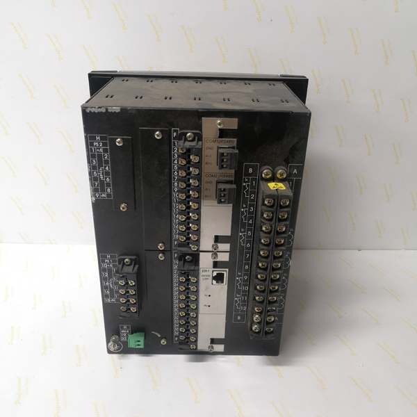
- Slot F I/O: 16 Digital Inputs + 8 Form-C Outputs (Option 1 board)
- Slot G I/O: None (0)
- Total I/O Capacity: 16 Digital Inputs + 8 Digital Outputs
- Communication: Redundant 10/100BaseTX Copper Ethernet (2 RJ45 ports) + Front RS232/USB Port + Graphic Display
- Protocols: IEC 61850 Edition 2, Modbus RTU/TCP, DNP 3.0 Level 2, IEC 60870-5-103/104, IEEE 1588 PTP
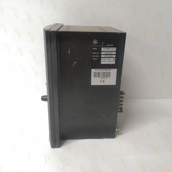
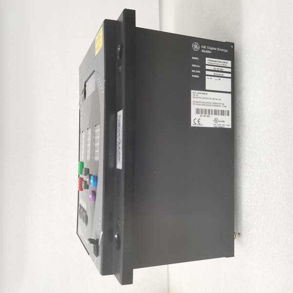
- Power Supply: 110-250V DC (88-300V range) / 120-230V AC (96-250V range), HI range
- Power Draw: 25-30 VA typical, 45 VA maximum
- Operating Temperature: -40°C to +70°C
- Isolation Rating: 2000V AC RMS I/O-to-chassis
- Dimensions: 168 × 150 × 55 mm (½ 19″ rack, 6U high)
- Weight: 5 kg (11 lbs)
- Language: English only (graphic display model)

The Real-World Problem It Solves
Critical substations can’t afford network downtime, but copper Ethernet is vulnerable to EMI in high-noise environments. This unit delivers dual redundant copper ports with PRP/HSR protocols, graphic display for operator situational awareness, and enhanced USB port for rapid field access—eliminating single points of failure in communication while maintaining cost-effective copper infrastructure.
Where you’ll typically find it:
- EHV transmission substations with copper-based IEC 61850 process bus requiring N-1 redundancy
- Industrial plants with moderate EMI environments where fiber installation is cost-prohibitive
- Critical feeder protection schemes requiring zero communication downtime with copper infrastructure
- Utility retrofits upgrading from single-port relays to redundant communication
This configuration combines cost-effective copper redundancy with advanced visualization and enhanced field access, ideal for applications where reliability meets operational practicality.
Hardware Architecture & Under-the-Hood Logic
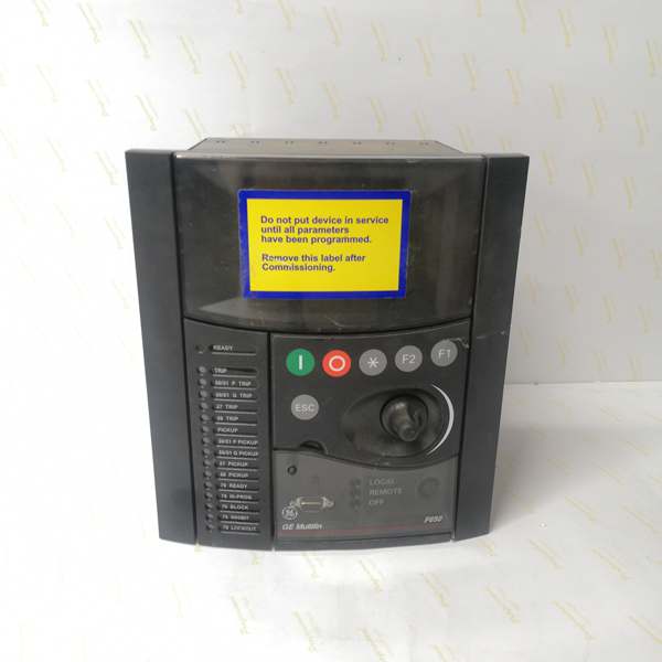
This is a graphic display F650 with redundant copper Ethernet and enhanced USB port. The “C” provides a 16×40 pixel graphic LCD with IEC symbols, “F” means no rear serial ports, “B” is 10/100BaseTX Ethernet, “10N” adds a redundant second copper port, and “BA” indicates enhanced display with front USB.
- Main CPU Board: 32-bit RISC processor (>50 MIPS) with 32MB+ flash memory, executing protection algorithms at 1ms scan cycles
- DSP Module: Handles analog-to-digital conversion at 64 samples per power cycle for current/voltage inputs
- Slot F I/O Board (Option 1): 16 digital inputs (24V DC programmable) + 8 Form-C relay outputs (6A @ 250V AC), communicates via CAN bus
- Slot G: Unpopulated—no I/O board installed
- Graphic Display Module: 16×40 pixel (240×128) graphic LCD with IEC symbols, supports single-line diagram visualization, programmable buttons and shuttle control
- Enhanced Display USB Controller: Front USB port supporting RS232/USB protocol for direct EnerVista connection without rear port access
- Communication Module: Dual redundant 10/100BaseTX copper Ethernet ports (2 RJ45), supports IEEE 1588 PTP time synchronization and PRP/HSR network redundancy
The redundant copper ports support PRP (Parallel Redundancy Protocol) or HSR (High-availability Seamless Redundancy) for seamless failover. PRP sends identical frames over both copper ports simultaneously—the receiving device discards duplicates. HSR creates a ring topology with intelligent forwarding. The enhanced USB port provides direct EnerVista access for configuration, firmware updates, and diagnostics without requiring cabinet access to rear ports. The graphic display renders substation single-line diagrams with IEC 61850 symbols, providing operators with real-time bay status. IEEE 1588 PTP over the redundant copper network provides microsecond-level time synchronization.
Field Service Pitfalls: What Rookies Get Wrong
Enhanced USB Port vs. Graphic Display Confusion
Techs see “Graphic Display” and assume full HMI capabilities. The “BA” configuration means graphic display PLUS enhanced USB—two separate features. The USB is for EnerVista connection, not for running HMI graphics on a laptop.
Field Rule: The graphic display (16×40 pixels) shows static single-line diagrams on the relay faceplate. The enhanced USB port connects your laptop to EnerVista for configuration and diagnostics. These are separate functions—don’t expect the USB port to mirror the graphic display to your screen. Use the front USB with GE0100-0001 cable for EnerVista access. Configure the single-line diagram in EnerVista Graphic Editor before uploading to the relay. Document which features are local display vs. remote configuration.
Redundant Copper PRP/HSR Network Design Errors
Techs connect both RJ45 ports to the same switch or different VLANs without proper protocol configuration. The “10N” ports are designed for PRP or HSR redundancy, not independent networks.
Field Rule: Configure PRP or HSR in EnerVista Communication settings. For PRP, connect each port to separate independent switches—both transmit identical frames. For HSR, configure a ring topology with all IEDs connected. Don’t use separate VLANs without proper protocol setup—PRP/HSR require specific frame handling. Test failover by unplugging one RJ45 while monitoring SCADA—communication should continue within 50ms. Document the redundancy protocol in your network topology diagram.
No Rear Serial Ports Limits Engineering Access
The “F” configuration means no rear RS485 ports. Rookies plan for local engineering stations via rear serial and find only front RS232/USB available.
Field Rule: Plan engineering access around available ports. With no rear serial, you have three options: (1) Front RS232 port for local connection, (2) Redundant copper Ethernet for network access, or (3) Enhanced front USB port for EnerVista. Document which method serves which function. Don’t assume rear serial exists. For sites requiring direct local access without network, use the front USB port—it’s faster and more reliable than RS232.
USB Port Firmware Upgrade Stability
Upgrading firmware via the front USB port can be unstable if using generic USB-serial converters. The “BA” enhanced display requires specific USB handling for reliable upgrades.
Field Rule: Always use GE USB-to-Serial cable part number GE0100-0001 for firmware upgrades. Generic converters impose different bus loads that can cause communication drops mid-upload. Before upgrading: verify uninterrupted AC/DC power, close EnerVista on all other PCs, disable Windows power saving on USB ports. Never interrupt an upload—if it hangs, wait 15 minutes before power cycling. The enhanced USB controller has specific timing requirements during firmware updates.
Redundant Ethernet Bandwidth Doubling Effect
PRP mode sends duplicate frames over both ports, doubling network traffic. Rookies don’t account for this and experience switch buffer overruns.
Field Rule: Calculate bandwidth with redundancy multiplier. If base traffic is 10Mbps, plan for 20Mbps with PRP. Use gigabit switches for aggregation points. Monitor switch port statistics during commissioning—high packet loss or buffer overruns indicate insufficient capacity. Reduce GOOSE publish frequency or consolidate messages if bandwidth is limited. Document bandwidth calculations in your network design specification.
Graphic Display Symbol Configuration
Techs upload custom single-line diagrams without verifying IEC symbol compatibility. The “C” graphic display includes IEC 61850 standard symbols—custom symbols may not render correctly.
Field Rule: Use IEC 61850 standard symbols from GE’s library. Custom symbols require approval from utility engineering department. Verify symbol colors and meanings match operator training. Keep diagrams simple—240×128 pixels has limited resolution. Test the uploaded diagram on the relay before final deployment. Document any custom symbol definitions in your operator manual.
Ground Loops with Dual Copper Connections
Two separate copper connections to different switches can create ground loops. Rookies experience intermittent communication during ground potential shifts.
Field Rule: Verify both Ethernet switches share a common ground reference. Measure potential difference between switch chassis—anything above 5V AC indicates risk. Use shielded Cat6 cables with proper grounding at both ends. If ground loops persist, use one port as primary and keep the second as hot-standby, or isolate one switch ground. Document grounding architecture in commissioning package.
Heat Dissipation with Redundant Communication and USB
Dual copper ports, graphic display, and enhanced USB controller add to thermal load. Rookies pack this relay into hot cabinets without considering higher power draw.
Field Rule: Measure cabinet ambient under full load. If it exceeds 50°C, install forced ventilation. Leave 15mm clearance around the relay. The redundant ports and graphic display add approximately 5-10 VA to base load. Monitor internal temperature in EnerVista—should stay below 70°C. For high-ambient installations (55°C+), consider external cooling or derate the relay.
Redundant Port LED Behavior Interpretation
Both RJ45 ports have TX/RX LEDs. Rookies misinterpret PRP mode LED patterns, assuming one dark port means failure.
Field Rule: In PRP mode, both ports transmit continuously—TX LEDs solid on both. RX LEDs flash as frames are received. If one port’s RX goes dark but the other remains active, redundancy is working (one path failed). If both RX go dark, communication is lost. In HSR mode, LED patterns differ based on ring topology. Document expected LED behavior for your protocol. Test failover by disconnecting one cable and verifying continued operation.
Trip Circuit Supervision Assumption with Slot F Option 1
This model uses Slot F Option 1 (16DI/8DO), which lacks dedicated trip supervision circuits. Rookies assume supervision exists and leave breakers unmonitored.
Field Rule: Slot F Option 1 provides standard I/O, not supervision. If trip circuit monitoring is required, specify Option 2 board (8DI/8DO+2 supervision) or implement using standard inputs with external relays. Verify Option number before ordering—”1″ in the order code = no supervision. Document supervision design in your protection scheme.
Commercial Availability & Pricing Note
Please note: The listed price is for reference only and is not binding. Final pricing and terms are subject to negotiation based on current market conditions and availability.


