
Description
Hard-Numbers: Technical Specifications
- Protection Functions: Overcurrent (50/51), Earth Fault (50N/51N), Sensitive Ground Fault (50SG/51SG), Directional Elements (67P/67G), Overvoltage/Undervoltage (59/27), Frequency (81U/O), Breaker Failure (50BF), Auto-Recloser (79), Synchrocheck (25)
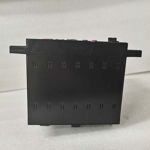
- Slot F I/O: 32 Digital Inputs (Option 4 board) + 0 Digital Outputs
- Slot G I/O: None (0)
- Total I/O Capacity: 32 Digital Inputs + 0 Digital Outputs
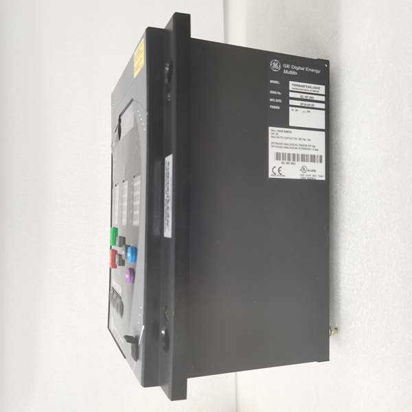
- Communication: Rear 100BaseFX Glass Fiber Optic Ethernet (COM3) + Front RS232/USB Port (COM2) + No rear serial ports, no copper Ethernet
- Protocols: Modbus RTU/TCP, DNP 3.0 Level 2, IEC 60870-5-104, IEC 61850 Ed.2 (optional)
- Power Supply: 110-250V DC (88-300V range) / 120-230V AC (96-250V range), HI range
- Power Draw: 20-25 VA typical, 40 VA maximum
- Operating Temperature: -40°C to +70°C
- Isolation Rating: 2000V AC RMS I/O-to-chassis
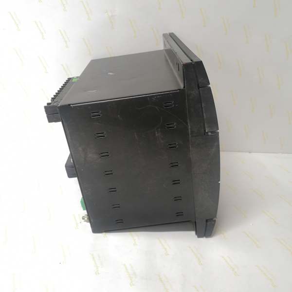
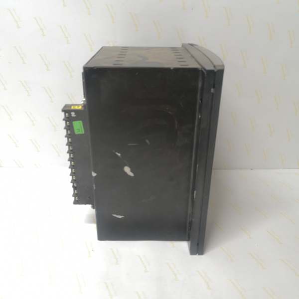
- Dimensions: 168 × 150 × 55 mm (½ 19″ rack, 6U high)
- Weight: 5 kg (11 lbs)
- Language: Chinese/English dual support

The Real-World Problem It Solves
Industrial plants with high EMI—VFD drives, large motors, welding operations—corrupt copper Ethernet and kill communication. This unit provides glass fiber optic immunity with 32 input channels for comprehensive status monitoring in environments where copper networking fails.
Where you’ll typically find it:
- Heavy industrial facilities with extensive variable frequency drive installations
- Steel mills, mining operations, and petrochemical plants with high electrical noise
- Process plants requiring long-distance communication runs (>2km) without repeaters
- Chinese-speaking industrial sites with comprehensive equipment status monitoring
This configuration focuses on noise-immune status acquisition, making it ideal for EMI-intensive applications where reliability trumps control output functionality.
Hardware Architecture & Under-the-Hood Logic
This is an EMI-hardened status monitoring relay. The Option 4 board in Slot F packs 32 digital inputs, and the “D” Ethernet board provides glass fiber optic connectivity instead of copper, eliminating ground loops and EMI susceptibility.
- Main CPU Board: 32-bit RISC processor (>50 MIPS) with 32MB+ flash memory, executing protection algorithms while managing 32-input scanning via CAN bus
- DSP Module: Handles analog-to-digital conversion at 64 samples per power cycle for current/voltage inputs, independent of input board load
- Slot F I/O Board (Option 4): 32 digital inputs (24V DC programmable threshold) with individual debounce filtering, communicates via CAN bus to main CPU
- Slot G: Unpopulated—no I/O board installed
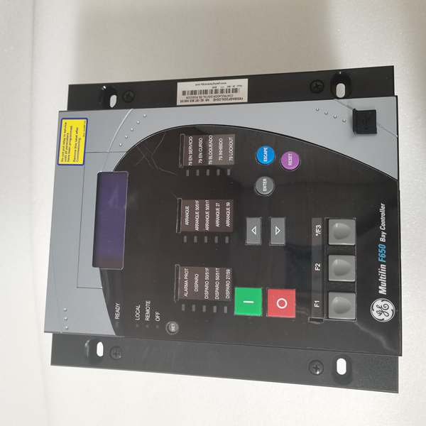
- Enhanced Display Module: 4×20 character alphanumeric LCD with front USB port supporting RS232/USB protocol
- Communication Module: 100BaseFX glass fiber optic Ethernet controller (ST connector, 1300nm, 62.5/125μm or 50/125μm multimode), no copper Ethernet port
- Power Supply Module: Switching-mode power supply with >80% efficiency, lower VA draw due to zero output load
The 100BaseFX glass fiber port supports distances up to 2km on multimode fiber without repeaters, compared to 100m maximum for copper Ethernet. The fiber port provides complete galvanic isolation (2000V+) between the relay and the network, eliminating ground loop problems common in industrial plants. The 32 inputs are organized as four groups of eight, with individual debounce timers and programmable voltage threshold detection (20-300V DC range). Since there are no outputs, CPU loading is dominated by input scanning—critical protection inputs can be prioritized with faster debounce times while auxiliary status inputs use longer filtering.
Field Service Pitfalls: What Rookies Get Wrong
Fiber-Only Configuration ConfusionTechs see an Ethernet port designation and expect RJ45 copper. The “D” board is glass fiber ONLY—no copper port available. Rookies show up with Cat5 cable and wonder why nothing fits.
Field Rule: Verify your media before arriving on site. The “D” board has ST connectors for glass fiber, not RJ45 for copper. Use 62.5/125μm or 50/125μm multimode fiber at 1300nm wavelength. If you need copper connectivity, specify F650-B-F-B or F650-B-F-C instead. Document fiber type and connector style in your bill of materials—don’t assume the site has compatible fiber infrastructure.
ST Connector Cleaning and Handlingthe key, causing connector damage or poor signal.
Field Rule: Learn ST connector technique. Align the key on the connector body with the keyway on the port. Push straight in until seated, then rotate the bayonet collar clockwise to lock. Never force— resistance means misalignment. Clean connectors with 99% isopropyl alcohol and lint-free wipes before mating. Check the ferrule end face for scratches or contamination under a microscope if available. Damaged ST connectors are cheap—replace rather than risk the entire fiber link.
Glass Fiber vs. Plastic Fiber ConfusionThe “D” board uses glass fiber (multimode), not plastic fiber. Rookies order 1mm plastic fiber by mistake and wonder why it doesn’t work.
Field Rule: Glass fiber uses 62.5/125μm or 50/125μm core/cladding diameters with ST connectors. Plastic fiber uses 1mm core with different connectors. They’re not interchangeable. Verify fiber specifications before ordering cable. This relay requires glass fiber—plastic fiber won’t couple properly and won’t pass light. Document “glass multimode fiber” explicitly in your cable specifications.
32 Input Debounce CPU Loading32 inputs with aggressive debounce times can overload the CPU. Rookies set all inputs to 5ms debounce “for fast response” and cause protection scan time degradation.
Field Rule: Prioritize your debounce settings. Critical protection inputs (breaker status, trip feedback) get 5-10ms. Permissive signals get 10-20ms. Slow auxiliary signals (door position, temperature) get 30-50ms. In EnerVista, monitor CPU loading—if it exceeds 70%, increase debounce times on non-critical inputs. You don’t need millisecond response on a door position switch.
Quasi-Analog Voltage Detection OverlookedThe Option 4 board supports programmable voltage thresholds (20-300V DC). Techs treat all 32 inputs as dry contacts and miss the capability to detect specific voltage levels.
Field Rule: If you need to detect 24V, 48V, or 125V DC levels without external transducers, configure inputs as “Quasi-Analog” in EnerVista with appropriate thresholds. This lets the relay detect voltage presence/absence directly. Document which inputs use threshold detection—future techs won’t expect 125V on a digital input terminal. Use this feature to eliminate external voltage sensing relays where possible.
Fiber Signal Loss TroubleshootingWith fiber-only communication, a break or dirty connector means total loss of SCADA access. Rookies don’t have backup communication plans and get stranded with no remote access.
Field Rule: Always maintain a backup communication path. Use the front USB port for local EnerVista access if fiber fails. Carry a fiber optic power meter and visual fault locator for troubleshooting. Document the fiber route and test points—if communication drops, check signal strength at the relay first (-10 to -20 dBm TX expected), then trace forward. Keep spare ST connector assemblies and fusion splicing tools on hand for critical sites.
Language Setting with Chinese SupportThis model includes Chinese/English support (C in order code). If the site is in China but the display is in English, operators can’t read fault codes during emergencies.
Field Rule: First power-up: press ESC, navigate to Settings > Language, select appropriate language (Chinese for mainland sites, English for international). This setting survives firmware updates. Provide bilingual labeling in multilingual sites. Nothing worse than troubleshooting a fault code the operator can’t read.
No Copper Ethernet Means No Direct Laptop ConnectionTechs are used to plugging a laptop directly into relays for configuration. With fiber-only Ethernet, this isn’t possible without media converters.
Field Rule: For on-site configuration, use the front USB port with GE0100-0001 cable. If you need Ethernet access for testing, bring a fiber-to-copper media converter. Don’t try to retrofit copper connectivity—use the designed USB port. Plan your test setup before arriving—know whether you’ll need USB, fiber, or both. Document the required test equipment in your commissioning package so future techs come prepared.
Firmware Upgrade via Fiber InstabilityUpgrading firmware over fiber can be unstable if the fiber link has marginal signal quality. Rookies ignore minor signal degradation and get stuck mid-upgrade.
Field Rule: Verify fiber signal quality before firmware upgrades. Measure RX power at the relay—should be -15 to -25 dBm for reliable operation. If below -30 dBm, clean connectors or repair the fiber first. Use USB as backup communication path if fiber upgrade fails. Never interrupt an upgrade—if it hangs, wait 15 minutes before power cycling. The bootloader has recovery routines, but marginal fiber links increase timeout risks.
Commercial Availability & Pricing NotePlease note: The listed price is for reference only and is not binding. Final pricing and terms are subject to negotiation based on current market conditions and availability.


