
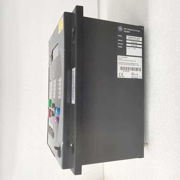
Description
Hard-Numbers: Technical Specifications
- Protection Functions: Overcurrent (50/51), Earth Fault (50N/51N), Sensitive Ground Fault (50SG/51SG), Directional Elements (67P/67G), Overvoltage/Undervoltage (59/27), Frequency (81U/O), Breaker Failure (50BF), Auto-Recloser (79), Synchrocheck (25)
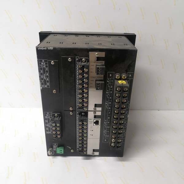
- Slot F I/O: 16 Digital Inputs + 8 Form-C Outputs (Option 1 board)
- Slot G I/O: 16 Digital Inputs + 8 Form-C Outputs (Option 1 board)
- Total I/O Capacity: 48 Digital Inputs + 16 Digital Outputs
- Communication: Rear 10/100BaseTX + 100BaseFX Fiber Optic Ethernet (COM3) + Front RS232/USB Port (COM2) + No rear serial ports
- Protocols: IEC 61850 Edition 2, Modbus RTU/TCP, DNP 3.0 Level 2, IEC 60870-5-104
- Power Supply: 110-250V DC (88-300V range) / 120-230V AC (96-250V range), HI range
- Power Draw: 30-35 VA typical, 50 VA maximum
- Operating Temperature: -40°C to +70°C
- Isolation Rating: 2000V AC RMS I/O-to-chassis
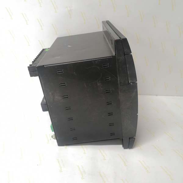
- Dimensions: 168 × 150 × 55 mm (½ 19″ rack, 6U high)
- Weight: 5 kg (11 lbs)
- Language: English only (no C language code in order code)

The Real-World Problem It Solves
High-voltage substations generate electrical noise that kills copper Ethernet, and critical protection schemes need deterministic peer-to-peer communication without RTU intermediaries. This unit delivers fiber optic immunity with IEC 61850 Ed.2 GOOSE messaging and dual-slot I/O density in a single chassis.
Where you’ll typically find it:
- EHV transmission substations with fiber optic process buses and IEC 61850 architecture
- Critical industrial facilities requiring EMI immunity and high-speed inter-device communication
- Generator plant protection schemes with fiber-based distributed control
- Utility interconnection points with strict cyber-security and isolation requirements
This configuration combines electromagnetic isolation, modern substation communication standards, and maximum I/O capacity for applications where reliability and security aren’t optional.
Hardware Architecture & Under-the-Hood Logic
This is a fully loaded F650 with dual I/O slots and dual Ethernet media. The main CPU manages protection logic while communicating with both I/O boards over CAN bus, and the fiber Ethernet module provides EMI-immune communication for IEC 61850 GOOSE messaging.
- Main CPU Board: 32-bit RISC processor (>50 MIPS) with 32MB+ flash memory, executing protection algorithms at 1ms scan cycles while managing dual I/O boards via internal CAN bus
- DSP Module: Handles analog-to-digital conversion at 64 samples per power cycle for current/voltage inputs, independent of I/O board load
- Slot F I/O Board (Option 1): 16 digital inputs (24V DC programmable) + 8 Form-C relay outputs (6A @ 250V AC), communicates via CAN bus
- Slot G I/O Board (Option 1): Identical to Slot F—16 digital inputs + 8 Form-C outputs, same CAN bus architecture
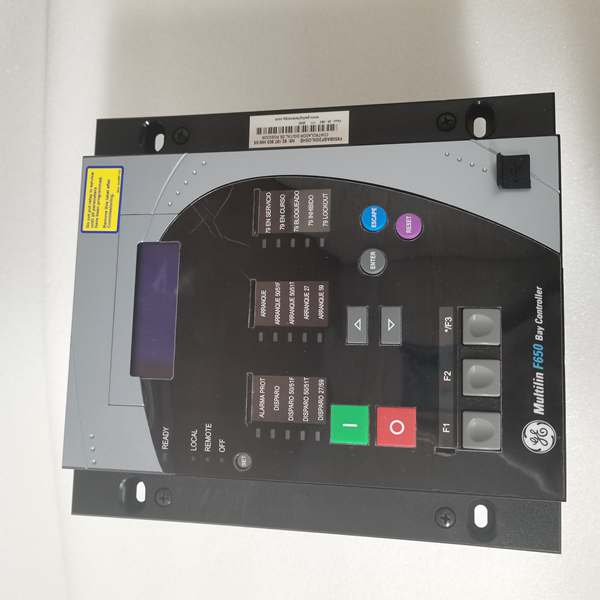
- Enhanced Display Module: 4×20 character alphanumeric LCD with front USB port supporting RS232/USB protocol
- Communication Module: Dual Ethernet controller—10/100BaseTX copper + 100BaseFX fiber optic (ST connector, 1300nm multimode), supports IEEE 1588 PTP time synchronization
- Power Supply Module: Switching-mode power supply with >80% efficiency, rated for higher VA draw due to dual I/O boards (up to 50 VA max)
The fiber optic port operates independently from the copper port, allowing simultaneous connection to two networks or redundant network topologies. IEC 61850 GOOSE messages can be transmitted over fiber with sub-millisecond latency, enabling direct peer-to-peer protection schemes without RTU involvement. The CAN bus handles both I/O boards at 1Mbps, ensuring synchronized state changes across all 48 inputs and 16 outputs. IEEE 1588 PTP (Precision Time Protocol) over the fiber network provides microsecond-level time synchronization across all IEDs in the substation.
Field Service Pitfalls: What Rookies Get Wrong
Fiber Port Misidentification and Media SelectionTechs see two Ethernet ports and assume both are copper. The “C” in the order code means the rear Ethernet board has both 10/100BaseTX and 100BaseFX fiber ports. Rookies plug copper into a fiber port or use the wrong fiber type.
Field Rule: Identify your ports. The copper port is standard RJ45. The fiber port is an ST connector (not LC or SC). Use 62.5/125μm or 50/125μm multimode fiber at 1300nm wavelength. Single-mode fiber won’t work—this is multimode only. If you only need copper, that’s fine, but if you’re installing fiber, verify the fiber type before pulling cable. Document which port connects to which network in your test package.
IEC 61850 GOOSE Configuration OverloadIEC 61850 Edition 2 supports complex GOOSE messaging with multicast. Rookies enable GOOSE on all 16 outputs without planning bandwidth, flooding the network and causing communication drops.
Field Rule: Plan your GOOSE subscriptions. Only critical interlocking and protection signals need GOOSE. Use unicast (Modbus TCP) for routine status updates. In EnerVista’s IEC 61850 configuration tool, set appropriate GOOSE publish intervals—fast (2-4ms) for trip signals, medium (10-20ms) for interlocks, slow (100ms+) for status. Monitor network bandwidth during commissioning—if you’re exceeding 50% of available bandwidth, reduce GOOSE frequency or consolidate messages.
Dual I/O Slot Addressing Errors48 inputs and 16 outputs mean complex addressing. Rookies mix up Slot F and Slot G addresses in logic, causing inputs to read wrong values or outputs to fire on the wrong slot.
Field Rule: Map your I/O clearly. Slot F inputs: F1-F16. Slot F outputs: F17-F32. Slot G inputs: G1-G16. Slot G outputs: G17-G32. In EnerVista, the I/O configuration shows Slot F and Slot G as separate banks. Create a cross-reference table in your commissioning document showing logic variable → physical slot → terminal number. Never trust memory—always verify with the schematic.
Fiber Cleanliness and Signal LossFiber ports are sensitive to contamination. Rookies touch the fiber connector ends or leave dust caps off, causing signal loss and intermittent communication.
Field Rule: Treat fiber connectors like precision optics. Never touch the end face. Keep dust caps on when not connected. Clean connectors with 99% isopropyl alcohol and lint-free wipes before mating. Verify signal strength after connection—multimode fiber should show -10 to -20 dBm TX power and -15 to -25 dBm RX power at the relay. If RX power is below -30 dBm, you have a dirty connector, bad splice, or wrong fiber type.
IEEE 1588 PTP Time Sync IgnoredIEC 61850 requires precise time synchronization for event correlation. Rookies don’t configure PTP or set wrong master/slave hierarchy, causing event timestamps to drift and making fault analysis impossible.
Field Rule: Configure PTP during initial setup. Identify your PTP grandmaster clock (usually the substation GPS or NTP server). Set the F650 to PTP slave mode in EnerVista Communication settings. Verify time synchronization accuracy—should be within ±1 microsecond of the grandmaster. Document PTP hierarchy in your SCADA interface description (ICD) file. Without proper time sync, your event records are worthless for post-fault analysis.
Fiber Port LED Indicators MisinterpretedThe fiber port has TX/RX LEDs. Rookies see flashing lights and assume communication is working, but don’t verify actual data flow or error rates.
Field Rule: Learn the LED patterns. Solid TX = transmitting. Flashing RX = receiving data. If TX is solid but RX is dark, you’re talking but nobody’s listening (wrong VLAN, wrong multicast group). If both flash but no data transfers, check for CRC errors or packet loss. Use EnerVista’s communication diagnostics to view error counters—non-zero error counts mean problems. Verify communication with a packet sniffer if needed.
Power Supply Heat Loading with Dual I/O Boards48 inputs and 16 outputs generate more heat than single-slot configurations. Rookies pack the relay into a hot cabinet without ventilation, causing thermal shutdowns or intermittent faults.
Field Rule: Measure cabinet ambient under full load. If it exceeds 50°C, you need forced ventilation. Leave 10mm clearance around the relay for convection cooling. Don’t bundle wires against the ventilation slots. In EnerVista, monitor internal temperature—should stay below 70°C. For high-ambient installations (55°C+), consider derating the relay or using external cooling. Thermal stress kills electronics faster than electrical stress.
Firmware Upgrade via Dual Ethernet ComplicationsWith both copper and fiber ports connected, firmware uploads can fail if the wrong port is selected or if network topology causes routing conflicts.
Field Rule: Choose one communication path for firmware upgrades. Disconnect the fiber port and use only copper USB/Ethernet for updates. If using Ethernet for upgrades, ensure the selected port has a dedicated route to the upgrade server without VLAN segmentation blocking traffic. Never interrupt an upload—if it hangs, wait 15 minutes before power cycling. The bootloader has recovery routines, but network complexity increases failure risk. Simplify the path before upgrading.
Commercial Availability & Pricing NotePlease note: The listed price is for reference only and is not binding. Final pricing and terms are subject to negotiation based on current market conditions and availability.


