
Description
Hard-Numbers: Technical Specifications
- Protection Functions: Overcurrent (50/51), Earth Fault (50N/51N), Sensitive Ground Fault (50SG/51SG), Directional Elements (67P/67G), Overvoltage/Undervoltage (59/27), Frequency (81U/O), Breaker Failure (50BF), Auto-Recloser (79), Synchrocheck (25)
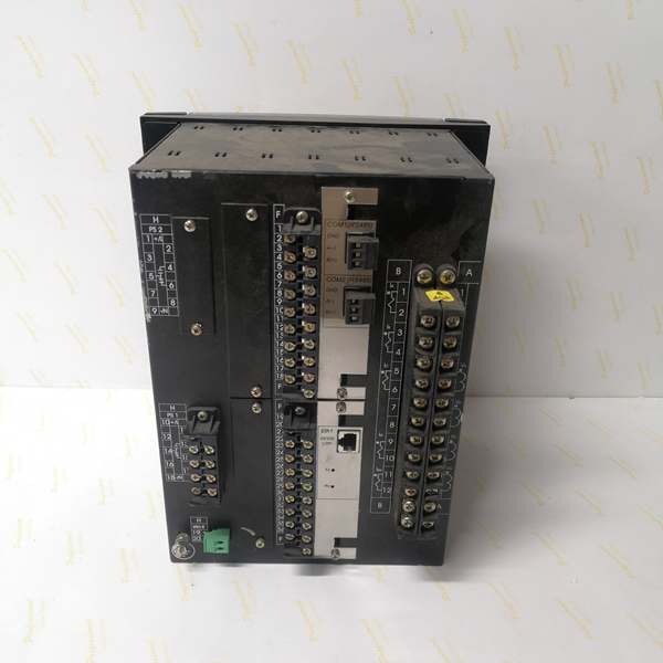
- Slot F I/O: 16 Digital Inputs + 8 Form-C Outputs (Option 1 board)
- Slot G I/O: 16 Digital Inputs + 8 Form-C Outputs (Option 1 board)
- Total I/O Capacity: 48 Digital Inputs + 16 Digital Outputs
- Communication: Rear 10/100BaseTX Ethernet (COM3) + Front RS232 Port (COM2) + No rear serial ports
- Protocols: Modbus RTU/TCP, DNP 3.0 Level 2, IEC 60870-5-104, IEC 61850 Ed.2 (optional)
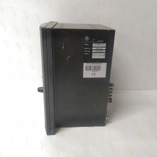
- Power Supply: 110-250V DC (88-300V range) / 120-230V AC (96-250V range), HI range
- Power Draw: 30-35 VA typical, 50 VA maximum (higher than single-slot models due to dual I/O boards)
- Operating Temperature: -40°C to +70°C
- Isolation Rating: 2000V AC RMS I/O-to-chassis
- Dimensions: 168 × 150 × 55 mm (½ 19″ rack, 6U high)
- Weight: 5 kg (11 lbs)
- Language: Chinese/English dual support

The Real-World Problem It Solves
Complex bus schemes and multi-breaker configurations eat up I/O points fast. This dual-slot configuration gives you 48 inputs and 16 outputs in a single relay chassis, eliminating the need for auxiliary I/O modules or multiple relay units for extensive interlocking and status monitoring.
Where you’ll typically find it:
- Double-bus or transfer bus substations with extensive breaker and disconnect status monitoring
- Ring bus schemes requiring multiple breaker interlocks and position indications
- Industrial plants with complex feeder automation and multiple motor starter interlocks
- Distribution substations requiring comprehensive local/remote switch position feedback
This configuration packs maximum I/O density into a standard 6U form factor, reducing panel footprint and wiring complexity for applications that would otherwise need multiple relays or external I/O expansion.
Hardware Architecture & Under-the-Hood Logic
This is a fully loaded F650 with both I/O slots populated. The main CPU manages protection logic while communicating with both Slot F and Slot G boards over the internal CAN bus, giving you the I/O capacity of two relays in one chassis.
- Main CPU Board: 32-bit RISC processor (>50 MIPS) with 32MB+ flash memory, executing protection algorithms at 1ms scan cycles while managing dual I/O boards via internal CAN bus
- DSP Module: Handles analog-to-digital conversion at 64 samples per power cycle for current/voltage inputs, independent of I/O board load
- Slot F I/O Board (Option 1): 16 digital inputs (24V DC programmable) + 8 Form-C relay outputs (6A @ 250V AC), communicates via CAN bus to main CPU
- Slot G I/O Board (Option 1): Identical to Slot F—16 digital inputs + 8 Form-C outputs, same CAN bus architecture
- Communication Module: 10/100BaseTX Ethernet controller on COM3, front RS232 on COM2, no rear serial ports
- Power Supply Module: Switching-mode power supply with >80% efficiency, rated for higher VA draw due to dual I/O board load (up to 50 VA max)
The internal CAN bus handles all communication between the CPU and both I/O boards at 1Mbps, ensuring synchronized state changes across all 48 inputs and 16 outputs. Each I/O board has its own microcontroller handling debounce, filtering, and output latching locally, reducing CPU interrupt load and ensuring deterministic response times even with maximum I/O configuration.
Field Service Pitfalls: What Rookies Get Wrong
I/O Addressing Confusion Between SlotsWith identical boards in Slot F and Slot G, techs mix up terminal assignments. Slot F uses terminals F1-F32, Slot G uses G1-G32. Rookies wire input 17 to the wrong slot and spend hours tracing dead circuits.
Field Rule: Label your terminal blocks clearly before pulling wires. Slot F inputs: F1-F16. Slot F outputs: F17-F32. Slot G inputs: G1-G16. Slot G outputs: G17-G32. In EnerVista, the I/O configuration shows Slot F and Slot G as separate banks—verify your point mapping matches the physical slot. Never assume Slot F and Slot G are interchangeable in logic.
Power Supply Margin Calculation FailureDual I/O boards draw more VA than single-slot models. Techs use the 30 VA spec from single-slot units and wonder why the relay reboots when all 16 outputs energize simultaneously.
Field Rule: Calculate load worst-case: (Number of simultaneously active outputs × 2W each) + base CPU load (14W) + display load (3W) + communications load (2W). For this dual-slot unit, budget 50 VA maximum. If you’re running all 16 outputs at 6A each, you’re pushing the limits. Consider external contactors for high-current loads or staggered output timing in logic.
CAN Bus Loading and Scan Time Degradation48 digital inputs means a lot of debouncing and filtering happening simultaneously. Improper debounce settings on multiple inputs can increase CPU loading and slow protection scan times.
Field Rule: Set debounce times appropriately—don’t use 50ms debounce on fast status signals. Critical protection inputs (breaker position, trip feedback) should have 5-10ms debounce. Slow auxiliary signals (door position, fan status) can use longer debounce. In EnerVista, monitor CPU loading指标—if it exceeds 80%, reduce debounce times or filter unnecessary inputs.
Terminal Block Screw Torque OverlookedMore terminals means more connection points. Rookies torque Slot F correctly but rush through Slot G, leaving loose connections that cause intermittent alarms on high-vibration equipment.
Field Rule: Use a calibrated torque screwdriver. GE spec: 0.5 N·m (4.4 lb-in) for terminal screws. Don’t guess by feel. After torqueing, pull-test each wire gently. On vibrating equipment (compressor stations, mills), consider torque seal or thread locker on critical connections. Document torque values in your commissioning package—future techs will thank you.
Heat Dissipation Blocked by Dense Wiring48 input/output wires packed into a ½ 19″ chassis create heat buildup. Rookies bundle all wires tightly against the relay case, blocking airflow and causing overheating in high-ambient cabinets.
Field Rule: Route wires away from the relay ventilation slots. Use the bottom cable entry if available. Don’t bundle wires directly against the relay housing—leave a 10mm air gap for convection cooling. In cabinets above 50°C ambient, consider forced ventilation or derate the relay. Monitor internal temperature in EnerVista—it should stay below 70°C under full load.
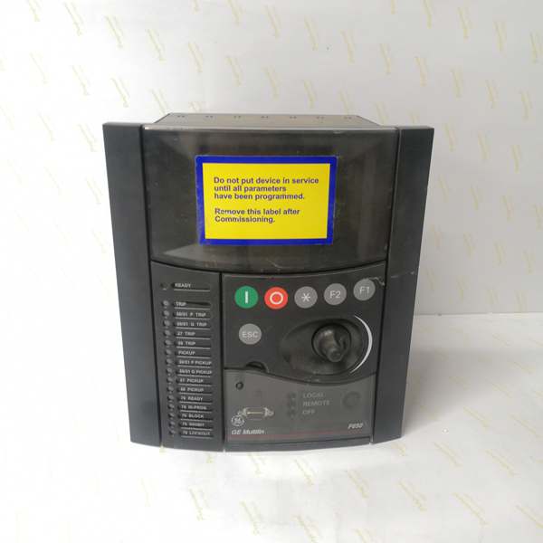
Language Setting OverlookedThis model includes Chinese/English support (C in order code). If the site is in China but the display is in English, operators can’t read fault codes during emergencies.
Field Rule: First power-up: press ESC, navigate to Settings > Language, select appropriate language (Chinese for mainland sites, English for international). This setting survives firmware updates. Document the language choice and provide bilingual labeling in multilingual sites. Nothing worse than troubleshooting a fault code the operator can’t read.
Commercial Availability & Pricing NotePlease note: The listed price is for reference only and is not binding. Final pricing and terms are subject to negotiation based on current market conditions and availability.


