
Description
Hard-Numbers: Technical Specifications
- Protection Functions: Overcurrent (50/51), Earth Fault (50N/51N), Sensitive Ground Fault (50SG/51SG), Directional Elements (67P/67G), Overvoltage/Undervoltage (59/27), Frequency (81U/O), Breaker Failure (50BF), Auto-Recloser (79), Synchrocheck (25)
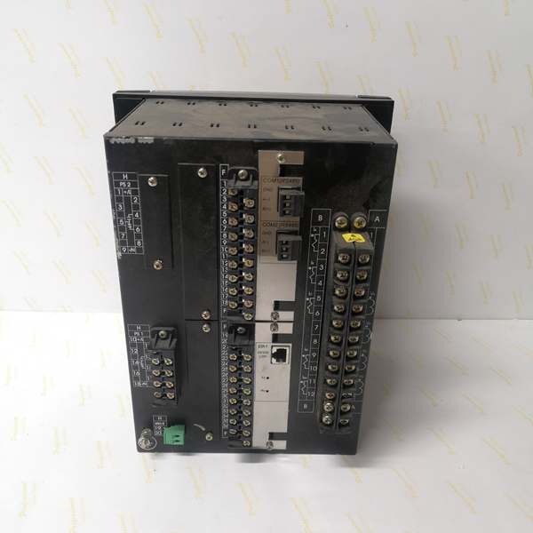
- Slot F I/O: 8 Digital Inputs + 6 Form-C Outputs + 2 Latching Current Sensing Outputs + 2 Trip/Close Supervision Circuits (Option 2 board)
- Slot G I/O: None (0)
- Communication: Rear 10/100BaseTX Ethernet (COM3) + Front RS232/USB Port (COM2) + No rear serial ports
- Protocols: Modbus RTU/TCP, DNP 3.0 Level 2, IEC 60870-5-104, IEC 61850 Ed.2 (optional)
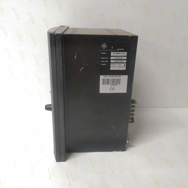
- Power Supply: 110-250V DC (88-300V range) / 120-230V AC (96-250V range), HI range
- Power Draw: 25-30 VA typical, 45 VA maximum
- Operating Temperature: -40°C to +70°C
- Isolation Rating: 2000V AC RMS I/O-to-chassis
- Dimensions: 168 × 150 × 55 mm (½ 19″ rack, 6U high)
- Weight: 5 kg (11 lbs)
- Language: English only (no C language code in order code)

The Real-World Problem It Solves
Breaker trip coil failures don’t announce themselves until you need to clear a fault. This unit integrates continuous trip/close circuit supervision directly into Slot F, monitoring coil integrity through voltage and current sensing so you catch the dead coil before the grid fault arrives.
Where you’ll typically find it:
- Municipal 11kV-35kV distribution substations with limited panel real estate
- Industrial plant feeder incoming cubicles replacing old electromechanical stacks
- Retrofit projects where breaker monitoring was previously an add-on relay
- English-speaking utility sites and industrial facilities
This configuration gives you supervision-grade protection in a single slot without sacrificing cabinet space or requiring external monitoring relays.
Hardware Architecture & Under-the-Hood Logic
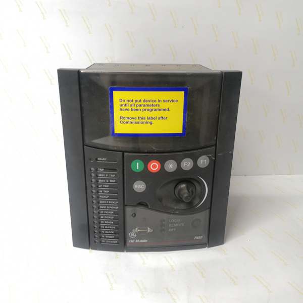
This isn’t just a protection relay—it’s a bay controller with its own 32-bit RISC processor running protection algorithms at 1ms scan cycles. The enhanced display module sits on the front board with its own USB controller, isolated from the protection CPU to prevent front-port faults from tripping the relay.
- Main CPU Board: 32-bit RISC processor (>50 MIPS) with 32MB+ flash memory, executing protection logic independently from display and communication modules
- DSP Module: Handles analog-to-digital conversion at 64 samples per power cycle for current/voltage inputs, offloading the main CPU for pure protection calculations
- Slot F I/O Board (Option 2): Contains two isolated supervision circuits (F1-F4, F15-F18) with voltage detectors, plus two latching current-sensing outputs (F31-F33, F34-F36) for monitoring supervision current flow
- Enhanced Display Module: 4×20 character alphanumeric LCD with front USB port supporting RS232/USB protocol—connects directly to EnerVista without touching rear ports
- Communication Module: 10/100BaseTX Ethernet controller on COM3, with no rear serial ports (F = None in order code)
- Power Supply Module: Switching-mode power supply with >80% efficiency, supports both AC and DC inputs with automatic voltage loss hold-up (200ms typical at 250VAC)
The supervision circuits work by applying a small supervision current through the trip coil path and monitoring voltage drop across the coil. If the path opens (coil burnout, wire break) or shorts, the supervision logic triggers an alarm within 2 seconds—before the breaker is called on to clear a fault.
Field Service Pitfalls: What Rookies Get Wrong
USB Port MisidentificationTechs see “Enhanced Display” and expect a graphical touchscreen like the M/N models. This unit still has a basic 4-line alphanumeric display—the “enhancement” is the front USB port, not the screen itself.
Field Rule: Use the front USB port with GE part number GE0100-0001 cable only. Generic USB-serial converters impose different bus loads that cause communication drops during firmware uploads. The USB port is for EnerVista access and firmware updates, not for running full HMI graphics.
Supervision Wiring Confusion on Option 2 BoardThe Slot F Option 2 board has two supervision groups—first group on terminals F1-F4, second on F15-F18. Rookies mix these up or only wire one group, leaving half the supervision circuit dead.
Field Rule: Wire both supervision groups. Group 1: F1-F2 and F3-F4. Group 2: F15-F16 and F17-F18. These are isolated voltage inputs—don’t parallel them. Test by pulling F1-F2 and verifying the relay alarms within 2 seconds. If no alarm, your supervision is bypassed and your breaker is unprotected.
Latching Outputs Misconfigured as Standard ContactsTerminals F31-F33 and F34-F36 are latching current-sensing outputs, not standard Form-C contacts like F19-F30. Configuring them as standard outputs causes erratic behavior during supervision testing.
Field Rule: In EnerVista, navigate to Settings > I/O > Contact Configuration and identify F31-F33 and F34-F36 as “Latching” outputs. These outputs latch ON when supervision current flows and drop out when supervision is interrupted. They’re status indicators, not control outputs. Don’t wire them to trip coils or interlocking relays.
Power Supply Range ViolationThe HI range accepts 88-300V DC or 96-250V AC. Techs sometimes measure 127V AC on a 120V nominal source and think they’re fine, but voltage sags during motor starts can drop below 96V, causing relay reboots.
Field Rule: Measure voltage at the relay terminals under worst-case load conditions, not just no-load. If your site dips below 96V AC or 88V DC during heavy motor starts, you need voltage regulation or a LO range unit with external boost converter. Undervoltage reboots corrupt settings and clear event records.
Firmware Upgrade InterruptionUpgrading via USB and losing connection halfway through leaves the relay in boot limbo. It won’t boot, it won’t communicate, and you’re pulling the module in a live cabinet.
Field Rule: Before any firmware upload: verify uninterrupted AC/DC power, use only GE0100-0001 USB cable, close EnerVista on all other PCs, and disable Windows power saving on the USB ports. Never interrupt an upload—if it hangs, wait 15 minutes before power cycling. The upgrade routine has recovery logic that needs time to complete.
Commercial Availability & Pricing NotePlease note: The listed price is for reference only and is not binding. Final pricing and terms are subject to negotiation based on current market conditions and availability.


