
Description
Hard-Numbers: Technical Specifications
- Protection Functions: Overcurrent (50/51), Earth Fault (50N/51N), Sensitive Ground Fault (50SG/51SG), Directional Overcurrent (67P/67N/67G), Overvoltage (59), Undervoltage (27), Frequency (81U/81O), Auto-Reclosing (79), Breaker Failure (50BF), Negative Sequence (46), Thermal (49), Synchrocheck (25), VT Fuse Failure
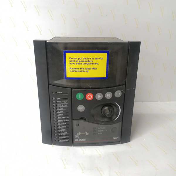
- Display: Basic Display (B) – 4-line alphanumeric LCD, Chinese/English dual language (C code)
- Communication Boards:
- Rear Serial Communications Board 1: None (F code)
- Rear Ethernet Communications Board 2 (B code): One 10/100BaseTX port (self-negotiable speed)
- Communication Protocols:
- Serial protocols: Modbus RTU, IEC 60870-5-103 (if rear serial board installed – not present in this configuration)
- Ethernet protocols: Modbus TCP/IP, DNP 3.0 Level 2, IEC 60870-5-104, IEEE 1588 (PTP) time synchronization, SNTP, web server support
- Digital I/O:
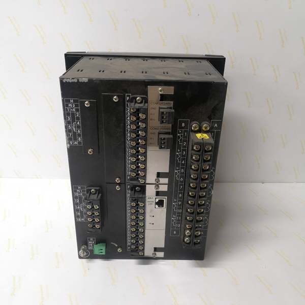
- Slot F (F1): 16 Digital Inputs + 8 Outputs
- Slot G (G0): None (empty slot)
- Total I/O Capacity: 16 Digital Inputs, 8 Digital Outputs
- Analog Inputs: 3-phase CT (1A/5A configurable, range 0.1-6000A), 3-phase VT (up to 208V L-N), 1 Neutral CT, 1 Sensitive Ground CT
- Power Supply:
- DC: 110-250V DC (range 88-300V DC)
- AC: 120-230V AC (range 96-250V AC)
- Power Consumption: 30W (typical at rated voltage)
- Operating Temperature: -40°C to +70°C
- Isolation Rating: 2000V AC RMS I/O-to-chassis, 1500V RMS channel-to-channel
- Dimensions: 19″ rack, 6U height
- Weight: 5 kg
- Front Ports: RS232 serial port for local configuration
- Event Recording: Up to 512 events with 1ms time-tag resolution
- Oscillography: Up to 5 seconds capture at maximum sample rate (64 samples/cycle), up to 512 records
- Trip Circuit Supervision: Not included in F1 I/O board (requires F2 board for dedicated TCS channels)
- Time Synchronization: IEEE 1588 (PTP), IRIG-B, SNTP support for precise event time tagging
- Language Support: Chinese/English (C code) – dual language interface for basic display and HMI
- Protocol Support: IEC 60870-5-103, Modbus RTU/TCP/IP, DNP 3.0 Level 2, IEC 60870-5-104 (C code configuration)

The Real-World Problem It Solves
Asian utility projects often require dual-language support for local operators who prefer Chinese interface, yet still need to communicate with English-speaking engineers during commissioning and maintenance. The F650BFBF1G0HIC solves this by providing Chinese/English dual language on the basic display while maintaining Ethernet-only communication with full protocol stack (Modbus, DNP3, IEC 60870-5-104) for SCADA integration. The C code configures the relay for IEC 60870-5-103 protocol support (legacy serial) alongside Modbus and DNP3, though without a rear serial board this support remains dormant unless an external serial-to-Ethernet converter is used. This configuration fits the Asian market standard where dual language is mandatory and IEC 60870-5-103 protocol is still widely deployed in older SCADA systems transitioning to Ethernet-based IEC 60870-5-104.
Where you’ll typically find it:
- 11kV-33kV distribution feeders in Asian utility substations (China, Southeast Asia) requiring Chinese language interface
- Industrial plants in China with multi-national teams needing dual language support
- Legacy SCADA modernization projects migrating from serial IEC 60870-5-103 to Ethernet IEC 60870-5-104
- Greenfield projects in Asian markets requiring compliance with local language regulations
- Retrofit installations replacing older relay brands with GE Multilin while maintaining existing SCADA protocol compatibility
Bottom line: This configuration bridges the gap between Asian utility requirements (Chinese language, IEC 60870 protocols) and modern Ethernet-based substation automation.
Hardware Architecture & Under-the-Hood Logic
The F650BFBF1G0HIC shares the same stripped-down architecture as other F1/G0 variants but differs in language configuration and protocol support. The lack of rear serial communication board (F code) means all communication flows through the single 10/100BaseTX Ethernet port (B code). The CPU module runs protection algorithms with 32-bit processing, while the basic display with Chinese/English language support (C code) provides localized operator interface. Slot F provides 16 digital inputs and 8 outputs (F1 board), while Slot G is empty (G0). The C code configures the internal protocol stack for IEC 60870-5-103, Modbus RTU/TCP/IP, DNP 3.0 Level 2, and IEC 60870-5-104, though IEC 60870-5-103 requires a rear serial board for active use.
Internal Signal Flow:
-
Analog Acquisition: CT and VT inputs connect to terminal blocks, pass through input transformers, and are digitized by 16-bit A/D converters at programmable sampling rates (up to 64 samples/cycle)
-
Phasor Processing: The CPU applies Discrete Fourier Transform (DFT) to extract fundamental frequency phasors from digitized samples, calculating magnitude, angle, and sequence components
-
Protection Element Evaluation: Phasor values feed into protection algorithms (overcurrent, directional, distance, frequency, voltage) running on parallel processing threads with scan cycle < 2ms for instantaneous protection
-
Programmable Logic Engine: User-configurable logic (IEC 61131-3 based) evaluates protection element outputs, digital inputs, and interlock conditions to determine trip/close decisions
-
Output Processing: Trip/close commands trigger Form-C relay outputs (8A @ 250V AC) with configurable pulse durations; outputs are isolated via optocouplers with 1500V RMS channel-to-channel isolation
-
Communication Processing: The single Ethernet port handles all external communication using the C code protocol stack: IEC 60870-5-104 (port 2404), Modbus TCP (port 502), DNP3 over TCP (port 20000), web server (port 80). IEC 60870-5-103 and Modbus RTU are configured in software but require rear serial board (not present) for actual operation. Time synchronization via IEEE 1588 (PTP), IRIG-B, or SNTP synchronizes internal clock for 1ms event tagging
-
Event Recording: Protection operations, state changes, and alarms are logged to non-volatile memory with 1ms timestamp resolution; up to 512 events and 512 oscillography records stored
-
Display Update: The basic 4-line LCD displays actual values, status, and alarms in Chinese or English (user-selectable) refreshed at 1Hz via internal serial bus from CPU to HMI controller. Language selection is configured via HMI menu or EnerVista 650 Setup software
Communication Architecture:
The C code configures a comprehensive protocol stack covering legacy and modern standards. Without a rear serial board (F code), legacy serial protocols (IEC 60870-5-103, Modbus RTU) are only accessible via external serial-to-Ethernet converters if required. Ethernet protocols operate on the single 10/100BaseTX port: IEC 60870-5-104 for SCADA master communication, Modbus TCP for PLC integration, DNP3 for North American-standard SCADA systems, and web server for browser-based monitoring. The Chinese/English language setting applies to display interface, alarm messages, and configuration menus, allowing operators to switch between languages without changing firmware or settings.
Field Service Pitfalls: What Rookies Get Wrong
Chinese Language Display on Basic 4-Line LCD
The C code provides Chinese/English language support on the basic 4-line alphanumeric display. Rookies expect a full graphical Chinese interface with complex characters, but the basic LCD only supports simplified Chinese characters within its 4×20 character limitation. They stare at the display trying to find graphical icons that don’t exist, or misinterpret truncated Chinese text that wraps incorrectly across lines. The Chinese character set is limited to 8-bit encoding, so some complex technical terms may appear as simplified or abbreviated forms.
Field Rule:
- Basic display = 4 lines x 20 characters maximum
- Chinese characters take 2 bytes per character, reducing effective display width to 10 Chinese characters per line
- Technical terms may be abbreviated in Chinese (e.g., “过流保护” instead of “过电流保护功能”)
- Use English language for detailed technical diagnostics, Chinese for alarm messages and basic status
- For full Chinese graphical interface, order M or N code variant (graphic display with Chinese support)
- Test language switching before commissioning: Press MENU → Settings → Language → Select Chinese/English
IEC 60870-5-103 Configured but No Serial Port
The C code includes IEC 60870-5-103 protocol support, a legacy serial protocol widely used in Asian utilities. Rookies see this in the configuration and assume they can connect directly to the SCADA master via IEC 60870-5-103. They design panel wiring with serial cables, terminate the RS485 bus, and then discover the relay has no rear serial communication board (F code). The protocol is configured in software but physically impossible to access without an external serial-to-Ethernet converter.
Field Rule:
- C code = IEC 60870-5-103 configured in software protocol stack
- F code = No rear serial board, so IEC 60870-5-103 cannot be used directly
- Check physical board configuration: Look at rear panel – no RS485 terminals means serial protocols unavailable
- If you need IEC 60870-5-103, either:
- Order F650 with A code (redundant RS485) instead of F code
- Use external serial-to-Ethernet gateway: Relay (Ethernet) → Gateway → SCADA Master (Serial IEC 60870-5-103)
- Verify protocol support: In EnerVista 650 Setup, check Communication → Protocol Settings – if protocol is grayed out, physical port doesn’t exist
Dual Language – Character Encoding Issues
The Chinese/English language support (C code) uses GB2312 encoding for Chinese characters. Rookies connect via web browser or EnerVista 650 Setup on a laptop configured for Unicode/UTF-8 and see garbled characters where Chinese text should appear. They think the relay is defective or the language setting is corrupted, but it’s actually a character encoding mismatch between the client software and the relay’s internal encoding.
Field Rule:
- F650 uses GB2312 encoding for Chinese characters (standard for mainland China)
- EnerVista 650 Setup: Configure Tools → Options → Character Encoding → GB2312/GBK for proper Chinese display
- Web browser: Set encoding to GB2312 or use browser auto-detect
- If characters still appear garbled, verify:
- Language setting on relay: MENU → Settings → Language → Chinese
- Regional settings on PC: Windows Region = China (Simplified)
- EnerVista software version: Older versions may have limited Chinese font support
- For international projects mixing Chinese and English, consider using English for technical documentation and Chinese only for operator-facing messages
Modbus RTU Over Ethernet Converter Required
Some Asian SCADA systems use Modbus RTU over serial RS485 despite having Ethernet infrastructure. Rookies see Modbus support in the C code configuration and attempt to run Modbus RTU directly over Ethernet. This fails because the Ethernet port only supports Modbus TCP, not Modbus RTU encapsulated in TCP packets. They spend hours troubleshooting Modbus connections that will never work without protocol conversion.
Field Rule:
- C code supports Modbus RTU (serial) and Modbus TCP (Ethernet)
- Without rear serial board (F code), Modbus RTU is physically unavailable
- Modbus over Ethernet is always Modbus TCP, not Modbus RTU over TCP
- If SCADA master requires Modbus RTU:
- Use serial-to-Ethernet gateway: SCADA Master (Serial Modbus RTU) → Gateway → Relay (Ethernet Modbus TCP)
- Configure gateway for protocol conversion: Modbus TCP to Modbus RTU
- Test gateway configuration: Verify data mapping between Modbus TCP registers and Modbus RTU registers
- For new installations, push SCADA vendor to use Modbus TCP or IEC 60870-5-104 instead of legacy serial protocols
IEC 60870-5-104 Common Address Configuration
The C code enables IEC 60870-5-104 protocol over Ethernet. Rookies configure the relay’s IEC 60870-5-104 settings with common address, but mismatch the address against the SCADA master configuration. Asian SCADA systems often use non-standard common addressing schemes (e.g., 2-byte common address, specific bit patterns), so the relay connects but never exchanges data. The rookie sees “Connected” status but no successful ASDUs (Application Service Data Units) transfer.
Field Rule:
- Verify SCADA master configuration: Common address format (1-byte or 2-byte), ASDU type, cause of transmission (COT) codes
- Configure relay: EnerVista 650 Setup → Communication → IEC 60870-5-104
- Common Address: Match SCADA master exactly (e.g., 0x0001 for relay 1)
- ASDU Type: Typically C_IC_NA_1 for interrogation, C_SC_NA_1 for single command, C_DC_NA_1 for double command
- Time Sync: Enable if SCADA master performs clock synchronization
- Test communication:
- Connect laptop with IEC 60870-5-104 test software (e.g., IEC 60870-5-104 Master Simulator)
- Send interrogation command (C_IC_NA_1), verify relay responds with all data points
- Send command (C_SC_NA_1), verify relay executes and returns confirmation
- Monitor ASDU traffic with Wireshark + IEC 60870-5-104 plugin to verify address matching
DNP3 Level 2 Index Mapping
The C code includes DNP3.0 Level 2 protocol support. Rookies familiar with North American DNP3 standards configure DNP3 index addresses starting from 0, but Asian SCADA systems often use 1-based indexing or custom index mappings. The rookie connects successfully but data points read back as wrong values or don’t map to expected SCADA tags.
Field Rule:
- Verify SCADA master DNP3 configuration: Index base (0 or 1), data point mapping, analog/digital object groups
- Configure relay: EnerVista 650 Setup → Communication → DNP3
- Object Groups: Typically Group 1 (binary inputs), Group 2 (binary outputs), Group 30 (analog inputs), Group 40 (analog outputs)
- Index Base: Match SCADA master (0 or 1)
- Variation: Standard variation (e.g., 2 for binary inputs with flags)
- Test DNP3 mapping:
- Use DNP3 test software (e.g., Triangle Microworks DNP3 Master Test Suite)
- Read all points, verify index addresses match expected values
- Write test commands, verify outputs activate correctly
- Document index mapping in commissioning report: Include DNP3 point list with relay indices vs. SCADA tag numbers
No Redundant Ethernet – Single Point of Failure
The B code provides one 10/100BaseTX Ethernet port with no redundancy. Rookies designing substation automation for critical feeders assume dual-port redundancy is standard. When the single Ethernet switch fails, they lose all SCADA communication and remote control capability. In Asian utilities where remote control is increasingly common, this can lead to extended outage times during switch failures.
Field Rule:
- Treat single Ethernet port as single point of failure
- Install two independent Ethernet switches on different power supplies
- Route network cables through different physical paths (avoid single conduit)
- Use managed switches with redundant power supplies
- If critical application requires network redundancy, order F650 with C/D/E/J/K/L/M code instead of B code
- Document failure mode: In switch failure scenario, local HMI still works, but remote control unavailable until network restored
Commercial Availability & Pricing Note
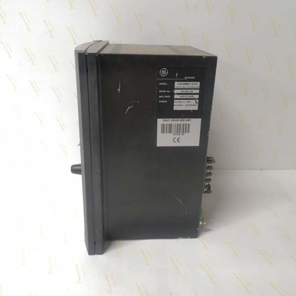
Please note: The listed price is for reference only and is not binding. Final pricing and terms are subject to negotiation based on current market conditions and availability. The F650BFBF1G0HIC is a base-configuration variant optimized for Asian markets with Chinese/English language support (C code) and comprehensive protocol stack (IEC 60870-5-103/104, Modbus RTU/TCP, DNP3.0). Lead times vary by supplier and region, with Asian distributors typically stocking this configuration (4-6 weeks for new units). Refurbished units may be available with shorter lead times. Always verify the exact model number and configuration with the supplier before purchase, as minor variations in order code (especially language and protocol configuration) significantly affect compatibility with local SCADA systems. The C code protocol configuration provides flexibility for both legacy serial (IEC 60870-5-103, Modbus RTU) and modern Ethernet (IEC 60870-5-104, Modbus TCP, DNP3) applications, but verify that the lack of rear serial board (F code) meets project requirements for serial protocol support.


