
Description
Hard-Numbers: Technical Specifications
- Protection Functions: Overcurrent (50/51), Earth Fault (50N/51N), Sensitive Ground Fault (50SG/51SG), Directional Overcurrent (67P/67N/67G), Overvoltage (59), Undervoltage (27), Frequency (81U/81O), Auto-Reclosing (79), Breaker Failure (50BF), Negative Sequence (46), Thermal (49), Synchrocheck (25), VT Fuse Failure
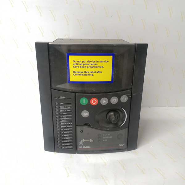
- Display: Basic Display (B) – 4-line alphanumeric LCD, English language
- Communication Boards:
- Rear Serial Communications Board 1: None (F code)
- Rear Ethernet Communications Board 2 (B code): One 10/100BaseTX port (self-negotiable speed)
- Communication Protocols: Modbus RTU, Modbus TCP/IP, DNP 3.0 Level 2, IEC 60870-5-104, IEEE 1588 (PTP) time synchronization, SNTP, web server support
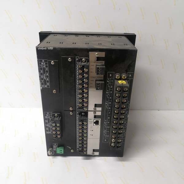
- Digital I/O:
- Slot F (F1): 16 Digital Inputs + 8 Outputs
- Slot G (G0): None (empty slot)
- Total I/O Capacity: 16 Digital Inputs, 8 Digital Outputs
- Analog Inputs: 3-phase CT (1A/5A configurable, range 0.1-6000A), 3-phase VT (up to 208V L-N), 1 Neutral CT, 1 Sensitive Ground CT
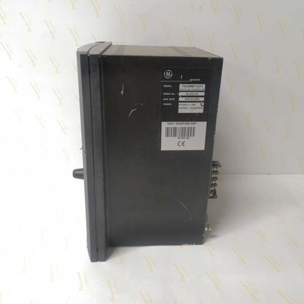
- Power Supply:
- DC: 110-250V DC (range 88-300V DC)
- AC: 120-230V AC (range 96-250V AC)
- Power Consumption: 30W (typical at rated voltage)
- Operating Temperature: -40°C to +70°C
- Isolation Rating: 2000V AC RMS I/O-to-chassis, 1500V RMS channel-to-channel
- Dimensions: 19″ rack, 6U height
- Weight: 5 kg
- Front Ports: RS232 serial port for local configuration
- Event Recording: Up to 512 events with 1ms time-tag resolution
- Oscillography: Up to 5 seconds capture at maximum sample rate (64 samples/cycle), up to 512 records
- Trip Circuit Supervision: Not included in F1 I/O board (requires F2 board for dedicated TCS channels)
- Time Synchronization: IEEE 1588 (PTP), IRIG-B, SNTP support for precise event time tagging

The Real-World Problem It Solves
Modern substation retrofits often face the nightmare of panel space constraints. You’re replacing old electromechanical relays with digital protection, but the existing cabinet is packed. The F650BFBF1G0HI solves this by fitting into a standard 6U rack mount while providing comprehensive feeder protection in a single unit. With no rear serial board (saving internal space) and a single Ethernet port for communication, it eliminates the need for external serial converters or additional communication equipment. The 16DI/8DO configuration handles most standard feeder applications without requiring external I/O expansion modules. This is the workhorse relay for straightforward feeder upgrades where cabinet space is tight and legacy serial communication isn’t required.
Where you’ll typically find it:
- 11kV-33kV distribution feeder retrofits replacing electromechanical relays in existing switchgear
- Industrial plant feeders with basic protection requirements and Ethernet SCADA integration
- Substation automation projects where all communication is Ethernet-based, no legacy serial devices
- Standard radial feeders with single breaker configurations requiring 16DI/8DO or fewer
- Small-to-medium substations with limited panel space and simple protection schemes
Bottom line: This configuration strips away unnecessary options to deliver reliable feeder protection in the smallest footprint possible for Ethernet-only environments.
Hardware Architecture & Under-the-Hood Logic
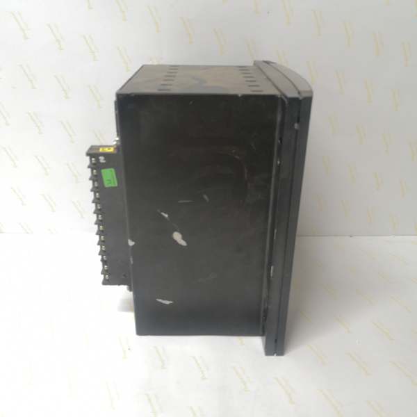
The F650BFBF1G0HI is a stripped-down digital bay controller built on the F650 platform. It lacks the rear serial communication board (F code), leaving only a single 10/100BaseTX Ethernet port (B code) for all communication. The CPU module runs protection algorithms with a 32-bit microprocessor, while the I/O section provides 16 digital inputs and 8 outputs via Slot F (F1 board). Slot G is empty (G0), keeping the unit compact. The basic display allows local monitoring without the overhead of graphical interfaces. Power comes from a high-voltage supply (HI) supporting both DC and AC sources.
Internal Signal Flow:
-
Analog Acquisition: CT and VT inputs connect to terminal blocks, pass through input transformers, and are digitized by 16-bit A/D converters at programmable sampling rates (up to 64 samples/cycle)
-
Phasor Processing: The CPU applies Discrete Fourier Transform (DFT) to extract fundamental frequency phasors from digitized samples, calculating magnitude, angle, and sequence components
-
Protection Element Evaluation: Phasor values feed into protection algorithms (overcurrent, directional, distance, frequency, voltage) running on parallel processing threads with scan cycle < 2ms for instantaneous protection
-
Programmable Logic Engine: User-configurable logic (IEC 61131-3 based) evaluates protection element outputs, digital inputs, and interlock conditions to determine trip/close decisions
-
Output Processing: Trip/close commands trigger Form-C relay outputs (8A @ 250V AC) with configurable pulse durations; outputs are isolated via optocouplers with 1500V RMS channel-to-channel isolation
-
Communication Processing: The single Ethernet port handles all external communication (Modbus TCP, DNP3, IEC 60870-5-104, web server, SNMP) using a dedicated communication processor; time synchronization via IEEE 1588 (PTP), IRIG-B, or SNTP synchronizes internal clock for 1ms event tagging
-
Event Recording: Protection operations, state changes, and alarms are logged to non-volatile memory with 1ms timestamp resolution; up to 512 events and 512 oscillography records stored
-
Display Update: The basic 4-line LCD displays actual values, status, and alarms refreshed at 1Hz via internal serial bus from CPU to HMI controller
Communication Architecture:
With no rear serial board, all external communication flows through the single 10/100BaseTX Ethernet port. The relay supports simultaneous protocol stacks: Modbus TCP (port 502), DNP3 over TCP (port 20000), IEC 60870-5-104 (port 2404), and web server (port 80). Time synchronization via IEEE 1588 (PTP) provides microsecond-level timing accuracy when a PTP Grandmaster is available on the network, or falls back to IRIG-B (via rear terminal) or SNTP. The lack of serial communication simplifies wiring but eliminates support for legacy serial SCADA protocols like Modbus RTU or IEC 103.
Field Service Pitfalls: What Rookies Get Wrong
Missing Serial Communication Board (F Code)
The F code means no rear serial communication board. Rookies see “F650” and assume every model has RS485 ports on the back. They design panel drawings with daisy-chained RS485 wiring, order cables, label them, and then discover the relay has zero serial terminals. This kills the schedule because now you need to redesign for Ethernet-only communication, which may require new switches and network architecture.
Field Rule: Always verify the rear serial communication code before panel design:
- F code = No serial ports, Ethernet only
- A code = Dual redundant RS485 ports
- P/G code = Fiber optic serial ports
- Check the order code, not just “F650”
- For F650BFBF1G0HI (F code), design Ethernet-only architecture
- If you need serial, you must order a variant with A/P/G/X/Y/Z/M code
Single Ethernet Port – No Redundancy
The B code provides one 10/100BaseTX port with no redundancy. Rookies used to dual-port switches or ring networks assume they have failover protection. When the single Ethernet switch fails or someone cuts the fiber, you lose all SCADA communication and remote control capability instantly. No backup path exists.
Field Rule:
- Treat the single Ethernet port as a single point of failure
- Install two independent Ethernet switches on separate power supplies
- Route network cables through different physical paths
- Use a managed switch with redundant power supplies and link aggregation if available
- If redundancy is critical, order F650 with C/D/E/J/K/L/M code instead of B
Empty Slot G Missed During I/O Allocation
The G0 code means Slot G is empty – no expansion board. Rookies familiar with G1 configurations (16DI/8DO expansion) assume they have 32 digital inputs and 16 outputs total. They design panel wiring for 32 inputs, label all the terminals, install the relay, and then find only 16 input points work. The rest are dead because there’s no expansion board to drive them.
Field Rule:
- G0 = Slot G empty, only Slot F provides I/O
- G1 = Slot G has 16DI/8DO expansion (total 32DI/16DO)
- Verify total I/O capacity: Slot F (always present) + Slot G (if G1)
- For F650BFBF1G0HI: 16 Digital Inputs, 8 Digital Outputs only
- If you need >16DI, order G1 variant or add external CIO module via CAN bus (requires rear serial board with CAN support – codes X/Y/Z/M)
IEEE 1588 (PTP) Time Sync Without Grandmaster
The B code Ethernet board supports IEEE 1588 (PTP) time synchronization. Rookies enable PTP in the relay settings but never install a PTP Grandmaster clock on the network. The relay spends minutes searching for a Grandmaster, fails to synchronize, and falls back to SNTP (less accurate) or internal clock drift. Event timestamps across multiple IEDs are inconsistent by seconds, breaking sequence-of-event analysis.
Field Rule:
- PTP requires a PTP Grandmaster (GPS-disciplined clock) on the network
- If you don’t have a Grandmaster, disable PTP and use IRIG-B or SNTP instead
- Verify PTP Grandmaster is broadcasting on the same VLAN/subnet
- Check PTP domain settings: Must match between Grandmaster and relay (typically domain 0)
- Test synchronization: Monitor PTP offset on relay HMI, should be < 1ms when synchronized
- If offset remains high, verify switch supports PTP transparent clock or configure E2E mode
Basic Display – No Single Line Diagrams
The B code is a basic 4-line alphanumeric display. Rookies used to graphic displays (M/N code) expect to see single-line diagrams, breaker status icons, and graphical metering. They stare at the 4-line LCD trying to find the breaker diagram that doesn’t exist. They waste time navigating text menus instead of getting the job done.
Field Rule:
- Basic display = Text only, no graphics, no single-line diagrams
- Use the keypad to navigate: Menu → Actual Values → Phasors/Status
- For advanced monitoring, connect via Ethernet and use EnerVista 650 Setup software on a laptop
- The web server (http://relay_IP) provides basic status and metering in a browser
- If you need graphical displays, order M or N code variant instead of B
Trip Circuit Supervision Not Available on F1 Board
The F1 I/O board provides 16 inputs and 8 outputs but does NOT include dedicated trip/close circuit supervision (TCS) channels. Rookies configure digital inputs for TCS and wire supervision across the trip coil, but they miss the critical timing and threshold settings needed for reliable TCS operation. The relay may fail to detect open trip circuits or generate nuisance alarms during breaker operation.
Field Rule:
- F1 board = No dedicated TCS channels; F2 board required for hardware TCS
- You can implement basic TCS using digital inputs, but configure carefully:
- Allocate 2 digital inputs for trip/close supervision (e.g., DI15, DI16)
- Connect supervision voltage across trip coil with 52a contact in series
- Configure supervision logic in programmable scheme: Alarm if supervision input de-energized for > 50ms
- Test by disconnecting trip coil: Verify alarm triggers within 100ms
- Note: This is software-based TCS, not hardware; timing and reliability differ from F2 board
- For mission-critical TCS requirements, order F2 board (code F2) instead of F1
No Enhanced Display USB Port
The model number lacks the E code, meaning no front USB port on the enhanced display. Rookies familiar with E variants expect to plug in a USB drive and pull event files or settings. They search the front panel for a USB port that isn’t there, wasting time before realizing they need to connect via RS232 or Ethernet to transfer files.
Field Rule:
- E code = Enhanced Display with front USB port
- No E code = Basic display with RS232 port only (or USB if basic display variant supports it)
- For file transfer: Connect laptop via front RS232 port (DB9) using EnerVista 650 Setup
- Alternative: Use Ethernet and TFTP or web browser file upload/download
- If you need front USB for quick file extraction, order variant with E code
Commercial Availability & Pricing Note
Please note: The listed price is for reference only and is not binding. Final pricing and terms are subject to negotiation based on current market conditions and availability. The F650BFBF1G0HI is a base-configuration variant with no rear serial board, single Ethernet port, and standard I/O (16DI/8DO), typically priced lower than expanded configurations. Lead times vary by supplier and region (typically 4-8 weeks for new units). Refurbished units may be available with shorter lead times. Always verify the exact model number and configuration with the supplier before purchase, as minor variations in order code (especially rear serial board and I/O expansion options) significantly affect functionality and I/O capacity. The lack of serial communication board simplifies installation for Ethernet-only environments but eliminates support for legacy serial protocols, so ensure compatibility with existing substation architecture before procurement.


