
Description
Hard-Numbers: Technical Specifications
- Protection Functions: Overcurrent (50/51), Earth Fault (50N/51N), Sensitive Ground Fault (50SG/51SG), Directional Overcurrent (67P/67N/67G/67SG), Overvoltage (59/59X), Undervoltage (27/27X), Frequency (81U/81O/81R), Auto-Reclosing (79), Breaker Failure (50BF), Negative Sequence (46), Thermal (49), Broken Conductor, Load Encroachment, VT Fuse Failure, Synchronism Check (25)
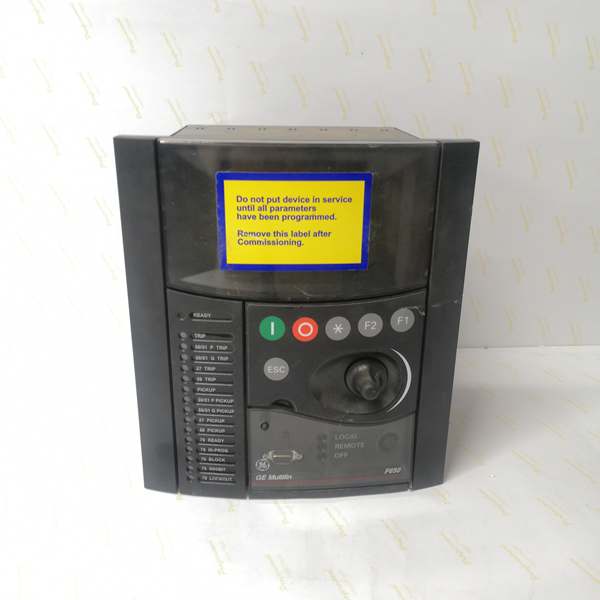
- Display: Basic Display (B) – 4-line alphanumeric LCD, English language
- Communication Boards:
- Rear Serial Communications Board 1: None (A code not present in order code)
- Rear Ethernet Communications Board 2 (C code): 1588, 10/100 Base TX + 100 Base FX (fiber optic)
- Communication Protocols: IEC 61850 Edition 2, Modbus RTU, Modbus TCP/IP, DNP 3.0 Level 2, IEC 60870-5-104, IEEE 1588 (PTP) time synchronization, PRP/HSR (IEC 62439-3), RSTP (IEEE 802.1D)
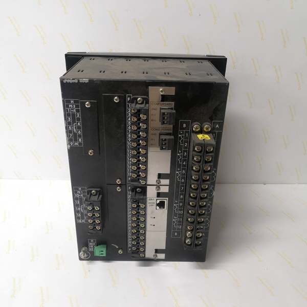
- Digital I/O:
- Slot F (F1): 16 Digital Inputs + 8 Outputs
- Slot G (G1): 16 Digital Inputs + 8 Outputs
- Total I/O Capacity: 32 Digital Inputs, 16 Digital Outputs
- Analog Inputs: 3-phase CT (1A/5A configurable, range 0.1-6000A), 3-phase VT (up to 208V L-N), 1 Neutral CT, 1 Sensitive Ground CT
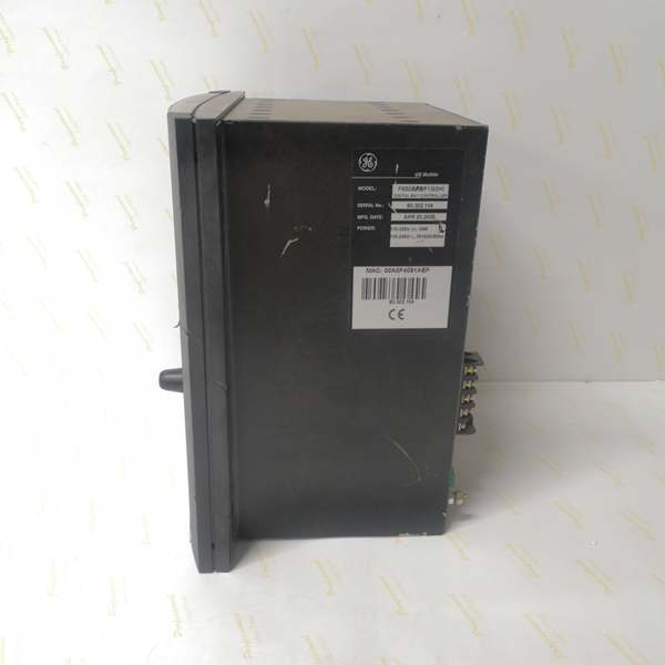
- Power Supply:
- DC: 110-250V DC (range 88-300V DC)
- AC: 120-230V AC (range 96-250V AC)
- Power Consumption: 30W (typical)
- Operating Temperature: -40°C to +70°C
- Isolation Rating: 2000V AC RMS I/O-to-chassis, 1500V RMS channel-to-channel
- Dimensions: 19″ rack, 6U height
- Weight: 5 kg
- Front Ports: RS232 serial port (for local configuration), Enhanced Display with USB port (E code)
- Event Recording: Up to 512 events with 1ms time-tag resolution
- Oscillography: Up to 5 seconds capture at maximum sample rate (64 samples/cycle), up to 512 records
- Trip Circuit Supervision: Not included in F1 I/O board (requires F2 board configuration for dedicated TCS channels)
- Time Synchronization: IEEE 1588 (PTP), IRIG-B, SNTP support for precise event time tagging across IEDs
- Language: English (language code not specified, default English for basic display)

The Real-World Problem It Solves
Modern substation automation requires extensive I/O capacity for monitoring complex breaker arrangements (GIS, ring bus, double-breaker configurations) with multiple status contacts, interlocks, and control outputs. The F650BACF1G1HI6E addresses this by providing 32 digital inputs and 16 digital outputs through Slot F (F1) and Slot G (G1) expansion boards, eliminating the need for external interposing relays or auxiliary I/O modules. The advanced Ethernet communication with fiber optic (100 Base FX) enables long-distance communication in noisy electrical environments where copper Ethernet is susceptible to electromagnetic interference. IEC 61850 Edition 2 support ensures seamless interoperability with multi-vendor substation automation systems, enabling GOOSE messaging for peer-to-peer protection and control without hardwired interlocks. The IEEE 1588 (PTP) time synchronization provides microsecond-level timing accuracy across all IEDs, critical for line differential protection and event sequence analysis.
Where you’ll typically find it:
- GIS substations with multi-position breakers requiring extensive status monitoring (open/closed positions, gas pressure, spring charging, motor status, local/remote selectors)
- Ring bus and double-breaker configurations requiring multiple interlock signals and parallel breaker control
- Substation automation projects with IEC 61850 Edition 2 requirement for GOOSE-based protection schemes
- Distribution feeders with high I/O demand (SCADA integration, breaker monitoring, transformer protection)
- Retrofits replacing multiple single-function relays with integrated protection and control
Key Differentiator: The G1 expansion board doubles I/O capacity to 32 inputs and 16 outputs, making this variant suitable for applications where G0 configurations would require external expansion modules or multiple relays. The combination of fiber optic Ethernet (100 Base FX) and IEC 61850 Edition 2 support makes it ideal for modern substation automation with harsh EMI environments and multi-vendor integration requirements.
Hardware Architecture & Under-the-Hood Logic
The F650BACF1G1HI6E is a modular digital bay controller built into a 19-inch rack, 6U height. The core components include a CPU module for processing protection algorithms and programmable logic, an Ethernet communication module with dual ports (10/100 Base TX copper + 100 Base FX fiber) supporting IEC 61850 Edition 2, Modbus TCP, DNP3 over TCP, and IEC 60870-5-104. Two I/O modules provide extensive digital I/O capacity: Slot F (F1) with 16 digital inputs and 8 outputs, Slot G (G1) with 16 digital inputs and 8 outputs. No rear serial communication board is installed (A code not present), relying entirely on Ethernet communication. The basic display allows local monitoring and configuration, enhanced with USB port for data transfer. Power is supplied via high-voltage input (110-250V DC or 120-230V AC).
Architecture Breakdown:
- CPU Module: 32-bit microprocessor executing protection algorithms (DFT-based phasor measurement, overcurrent, directional, distance elements) with scan cycle < 2ms for instantaneous protection
- Acquisition Modules: Digitize analog inputs from CTs and VTs at programmable sampling rates (up to 64 samples/cycle)
- Slot F I/O Module (F1): Provides 16 digital inputs for breaker status, interlocks, and control signals; 8 digital outputs for trip/close commands and alarms
- Slot G I/O Module (G1): Expansion module providing additional 16 digital inputs and 8 outputs, doubling total I/O capacity to 32DI/16DO
- Communication Module (C code – Ethernet Board 2): Dual-port Ethernet with 10/100 Base TX (copper) and 100 Base FX (fiber optic) supporting IEC 61850 Edition 2, Modbus TCP, DNP3 over TCP, IEC 60870-5-104
- No Serial Communication Board: A code not present in order code indicates no redundant RS485 serial ports installed; all communication via Ethernet
- Power Supply Module: Wide-range input (88-300V DC or 96-250V AC) with DC/DC conversion to internal voltages
- Front Panel Interface: Basic 4-line LCD display, keypad, 15 programmable LEDs, RS232 port for local configuration, USB port for enhanced display functionality (E code)
- Memory Modules: Non-volatile memory for settings, event records (512 events), oscillography data (up to 512 records)
- Protection Logic Engine: Programmable logic based on IEC 61131-3 standard, configurable via EnerVista 650 Setup software, supporting IEC 61850 GOOSE messaging for peer-to-peer protection and control
Protection Algorithm Flow:
CT/VT inputs → Analog-to-digital conversion (64 samples/cycle max) → Phasor extraction (DFT algorithm) → Protection element processing (overcurrent, directional, distance, etc.) → Programmable logic evaluation → Output decision → Trip/Close command to breaker + GOOSE message transmission to peer IEDs
Communication Architecture:
The relay supports dual Ethernet ports operating simultaneously: 10/100 Base TX copper for local substation LAN, 100 Base FX fiber for long-distance communication or EMI-resistant links. Protocol stack i
ncludes IEC 61850 Edition 2 (MMS, GOOSE, SV), Modbus RTU/TCP, DNP3.0 Level 2, IEC 60870-5-104 for SCADA integration. Time synchronization supports IEEE 1588 (PTP), IRIG-B, and SNTP for precise event time tagging across multiple IEDs with microsecond accuracy. PRP/HSR protocols provide network redundancy for critical applications, while RSTP prevents network loops.
IEC 61850 Edition 2 Integration:
- MMS (Manufacturing Message Specification): Client-server communication for SCADA integration, supporting file transfer, setting groups, and data access
- GOOSE (Generic Object Oriented Substation Event): Peer-to-peer messaging for protection and control without hardwired interlocks (e.g., breaker failure trip to adjacent breakers, interlocking, transfer trip)
- SV (Sampled Values): Streaming analog data for line differential protection or busbar protection applications
- SCL (Substation Configuration Language): ICD, CID, SSD, SCD files for system configuration and interoperability
Field Service Pitfalls: What Rookies Get Wrong
Missing Serial Communication Board (A code not present)
The F650BACF1G1HI6E has no rear serial communication board installed (A code not present in order code). Rookies assume all F650 relays have RS485 ports and design p
anel wiring with daisy-chained RS485 connections. When they attempt to connect serial devices, they find no RS485 terminals and must redesign the communication architecture to use Ethernet only. This causes project delays and requires retrofitting fiber optic cabling for long-distance communication.
- Field Rule: Verify communication board configuration before panel design:
- Check order code: Presence of “A” indicates redundant RS485 serial ports; absence means Ethernet-only communication
- For F650BACF1G1HI6E (no A code), design Ethernet-only communication architecture
- Use 10/100 Base TX copper for short distances (< 100m) within control room
- Use 100 Base FX fiber for long distances (> 100m) or high-EMI environments
- Configure IP addressing, subnet mask, and gateway for Ethernet communication
- Use Ethernet switches with redundant power supplies for substation LAN
- Test Ethernet connectivity before commissioning: ping, SNMP, IEC 61850 discovery
I/O Capacity Miscalculation (32DI/16DO vs. 16DI/8DO)
The G1 expansion board doubles I/O capacity to 32 digital inputs and 16 outputs. Rookies familiar with G0 configurations (16DI/8DO) may underallocate I/O points during panel design, assuming standard capacity. When wiring GIS breakers with multiple position indicators (open/closed/ground/isolator), gas monitoring, spring status, motor operation, and interlocks, they quickly exhaust 16 inputs and must add external I/O modules or reconfigure the scheme.
- Field Rule: Map all required I/O points before procurement:
- For G1 configuration (F650BACF1G1HI6E), total capacity: 32 Digital Inputs, 16 Digital Outputs
- Typical GIS breaker I/O allocation (example):
- Position 1: Open/Closed/Ground/Isolator (4 inputs)
- Position 2: Open/Closed/Ground/Isolator (4 inputs)
- Gas pressure: SF6 low/alarm/shutoff (3 inputs)
- Spring charging: Charged/charging motor status (2 inputs)
- Motor operation: Running/overheated/tripped (3 inputs)
- Local/remote selector (1 input)
- Trip circuit healthy (1 input)
- Close circuit healthy (1 input)
- Interlocks: Bus A/B sync, key transfer, zone select (4-6 inputs)
- Trip command (1 output)
- Close command (1 output)
- Alarm outputs: Gas low, motor fault, SF6 alarm (3-4 outputs)
- Status outputs: Breaker position 1/2 (2 outputs)
- Total estimate: 23-26 inputs, 8-11 outputs for GIS breaker with two positions
- G1 configuration (32DI/16DO) provides adequate capacity for most GIS and ring bus applications
- For complex schemes requiring >32DI, use CIO remote I/O module via CAN bus
Fiber Optic Connector Mismatch (100 Base FX)
The C code configuration includes 100 Base FX fiber optic port. Rookies assume ST connectors (common in older installations) but the relay may use SC connectors (more modern standard). Mismatched connectors require fiber optic patch cables or hybrid adapters, causing commissioning delays. Additionally, rookies may use multimode fiber for distances exceeding specification (multimode: 2km max, single-mode: 15km max), causing signal loss.
- Field Rule: Verify fiber optic specifications before installation:
- Confirm connector type: Most modern F650 variants use SC connectors; verify documentation
- Test fiber continuity with optical power meter: Transmit power -10 to -3 dBm, receive sensitivity -14 to -31 dBm
- Calculate link budget: TX power – RX sensitivity – connector loss (0.5dB per connector) – fiber attenuation (3dB/km for multimode, 0.5dB/km for single-mode)
- For distances < 2km: Use multimode fiber (62.5/125μm or 50/125μm)
- For distances 2-15km: Use single-mode fiber (9/125μm)
- Do not exceed maximum distances: Multimode 2km, Single-mode 15km
- Label fiber cables at both ends with relay ID, port ID, and destination
- Clean fiber connectors with lint-free wipes and isopropyl alcohol before connection
- Test link with Ethernet tester: Verify 100 Mbps link speed and CRC error count < 0
IEC 61850 GOOSE Subscription Failures
The IEC 61850 Edition 2 configuration enables GOOSE messaging for peer-to-peer protection. Rookies configure GOOSE publish settings correctly but fail to configure GOOSE subscriptions on receiving IEDs, resulting in protection scheme failures. Common errors include incorrect AppID, MAC address mismatch, VLAN misconfiguration, or failing to enable GOOSE on the receiving IED’s Ethernet port.
- Field Rule: Configure GOOSE publish and subscription systematically:
- Publish configuration (on F650BACF1G1HI6E):
- In EnerVista 650 Setup > IEC 61850 > GOOSE Control Blocks (GCB)
- Create GCB for breaker status, trip commands, interlocks
- Set AppID (unique hex identifier, e.g., 0x0001)
- Configure GOOSE ID (IED name + logical device + logical node)
- Set dataset: Include status points (DI1-DI32), command points (DO1-DO16)
- Configure TTL (Time To Live): Typically 2000ms
- Set Min Time: 2ms, Max Time: 1000ms
- Verify MAC address: Auto-generated from AppID (01:0C:CD:01:00:01 for AppID 0x0001)
- Subscription configuration (on receiving IEDs):
- Import SCL file (ICD or CID) from F650
- Configure IEC 61850 > GOOSE Subscriptions
- Map received GOOSE to internal binary inputs
- Verify AppID matches publisher configuration
- Enable GOOSE on Ethernet port
- Test by triggering GOOSE message: Verify subscriber receives and updates status
- Test GOOSE communication:
- Use IEC 61850 GOOSE analyzer (e.g., Wireshark with IEC 61850 plugin)
- Capture packets: Verify AppID, MAC address, dataset
- Monitor GOOSE publication interval: Should match configuration (typically 2-100ms)
- Test trip command: Verify subscriber activates protection output within 10ms
- Publish configuration (on F650BACF1G1HI6E):
Trip Circuit Supervision Not Available on F1 Board
The F1 I/O board (Slot F and Slot G) provides 16 digital inputs and 8 outputs but does NOT include dedicated trip/close circuit supervision (TCS) channels. Rookies configure digital inputs for trip circuit monitoring but fail to implement proper voltage sensing across the trip coil. When a trip coil opens, the relay doesn’t detect it until a fault occurs and the breaker fails to trip. With 32 digital inputs available, supervision can be implemented but requires careful configuration.
- Quick Fix: Use dedicated digital inputs for trip circuit supervision:
- Allocate two digital inputs (e.g., Slot F DI5, DI6) for trip/close circuit supervision
- Configure DI5 for trip circuit supervision: Connect across trip coil with 52a contact in series
- Configure DI6 for close circuit supervision: Connect across close coil with 52b contact in series
- In EnerVista 650 Setup, enable supervision logic in programmable scheme to alarm on loss of continuity
- Set supervision timing: Detect open circuit within 50ms
- Test by disconnecting trip coil wire: Relay should alarm “Trip Circuit Failure” within 50ms
- Note: F1 board supervision uses general-purpose digital inputs, not dedicated TCS channels—configure supervision timing and thresholds appropriately
- With 32 digital inputs available, allocate supervision inputs after critical status and interlock signals
IEEE 1588 (PTP) Time Synchronization Misconfiguration
The C code Ethernet board supports IEEE 1588 (PTP) time synchronization. Rookies configure PTP on the relay but fail to configure PTP Grandmaster on the network or use incompatible PTP profiles (default vs. power profile). This results in time synchronization failures, causing event sequence mismatches across IEDs and protection coordination issues.
- Field Rule: Configure IEEE 1588 (PTP) synchronization correctly:
- PTP Grandmaster configuration:
- Designate a GPS-disciplined clock as PTP Grandmaster (e.g., Meinberg, Symmetricom)
- Configure Grandmaster with Power Profile (IEEE C37.238) for substation applications
- Set PTP domain: Typically 0 for single-domain substation
- Configure PTP message intervals: Sync 8 messages/second, Announce 8 messages/second
- Enable E2E (End-to-End) transparent clock for Ethernet switches
- PTP Slave configuration (on F650BACF1G1HI6E):
- In EnerVista 650 Setup > Communication > Time Synchronization
- Enable IEEE 1588 (PTP) as primary time source
- Configure PTP profile: IEEE C37.238 (Power Profile)
- Set PTP domain: Match Grandmaster configuration (typically 0)
- Configure fallback time sources: IRIG-B, SNTP
- Set time accuracy requirements: ±1μs for line differential, ±1ms for general protection
- Test PTP synchronization:
- Monitor PTP status on relay HMI: Should show “PTP Synchronized” with offset < 1ms
- Capture event records from multiple IEDs: Verify timestamp consistency within 1ms
- Use PTP analyzer (e.g., Wireshark with PTP plugin) to verify Sync and Follow_Up messages
- Test PTP redundancy: Disconnect Grandmaster, verify switch to fallback time source
- PTP Grandmaster configuration:
No Redundant RS485 – Communication Single Point of Failure
The absence of rear serial communication board (A code not present) means the relay relies entirely on Ethernet communication. Rookies assume redundant serial ports are available for backup communication and design panels without Ethernet redundancy. If the Ethernet network fails (switch failure, cable cut), the relay loses all SCADA communication and remote control capability.
- Field Rule: Design Ethernet redundancy for critical applications:
- Network topology:
- Use PRP (Parallel Redundancy Protocol) or HSR (High Availability Seamless Redundancy) for seamless failover
- Configure dual Ethernet ports: Port 1 (copper) on VLAN A, Port 2 (fiber) on VLAN B
- Use redundant Ethernet switches with independent power supplies
- Route fiber cables through different physical paths (avoid single conduit)
- Configuration:
- Enable PRP/HSR in EnerVista 650 Setup > Communication > Ethernet
- Configure separate IP addresses for each Ethernet port
- Set PRP node table: Identify PRP-capable switches and IEDs
- Verify redundancy: Disconnect one network segment, verify communication continues without interruption
- Test failover:
- Monitor SCADA communication while disconnecting Ethernet switch A
- Verify communication switches to Ethernet port B within 50ms
- Reconnect switch A, verify communication returns to dual-port operation
- Record failover time: Should be < 100ms for PRP/HSR
- Network topology:
Firmware Upgrade via Front USB Port Only
The enhanced display with USB port (E code) enables firmware upgrades via front panel. Rookies attempt firmware upgrades via Ethernet (possible for some models) but fail to configure boot code upgrade sequence properly, causing relay to brick. The F650 requires specific upgrade sequence: boot code first, then firmware version.
- Field Rule: Follow correct firmware upgrade procedure:
- Pre-upgrade preparation:
- Download correct firmware and boot code files from GE website
- Verify firmware version compatibility: Match relay hardware version
- Backup current settings: Use EnerVista 650 Setup to export configuration (.ini file)
- Verify relay is in service mode (not protecting live equipment)
- Boot code upgrade:
- Connect to relay via front USB port
- Open EnerVista 650 Setup > File > Boot Code Upgrade
- Select boot code file (.hex)
- Initiate upgrade: Monitor progress bar, do not interrupt
- Wait for relay to reboot: Boot code upgrade takes 2-5 minutes
- Firmware upgrade:
- After successful boot code upgrade, reconnect via USB
- Open EnerVista 650 Setup > File > Firmware Upgrade
- Select firmware file (.hex)
- Initiate upgrade: Monitor progress bar, do not interrupt
- Wait for relay to reboot: Firmware upgrade takes 3-8 minutes
- Verify firmware version: Check relay HMI or EnerVista Setup > System Info
- Post-upgrade verification:
- Restore configuration: Import backed-up .ini file
- Verify all settings are applied correctly
- Test protection functions: Inject test currents, verify trip outputs
- Test communication: Verify Ethernet and IEC 61850 connectivity
- Document upgrade: Record firmware version, date, and results in commissioning log
- Pre-upgrade preparation:
Commercial Availability & Pricing Note
Please note: The listed price is for reference only and is not binding. Final pricing and terms are subject to negotiation based on current market conditions and availability. The F650BACF1G1HI6E is a high-configuration variant with G1 I/O expansion, advanced Ethernet communication (fiber optic + copper), and IEC 61850 Edition 2 support, typically priced higher than base models. Lead times vary by supplier and region (typically 6-10 weeks for new units). Refurbished units may be available with shorter lead times. Always verify the exact model number and configuration with the supplier before purchase, as minor variations in order code can significantly affect functionality and I/O capacity. The G1 expansion board and fiber optic Ethernet configuration add significant cost but eliminate the need for external I/O modules and fiber media converters in most substation applications.


