
Description
Hard-Numbers: Technical Specifications
- Protection Functions: Overcurrent (50/51), Earth Fault (50N/51N), Overvoltage (59), Undervoltage (27), Directional Overcurrent (67), Auto-Reclosing (79), Breaker Failure (50BF), Load Shedding, Remote Control, Sensitive Ground Fault, Negative Sequence (46), Thermal (49), Frequency (81)
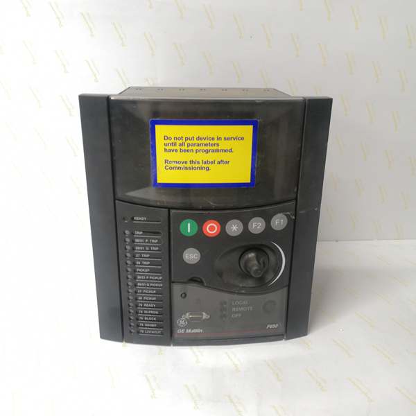
- Display: Basic Display (B) – 4-line alphanumeric LCD, English language
- Communication Boards:
- Rear Serial Communications Board 1 (A): Redundant RS485
- Rear Ethernet Communications Board 2 (B): 10/100 Base TX
- Communication Protocols: Modbus RTU, Modbus TCP/IP, DNP 3.0 Level 2, IEC 60870-5-104
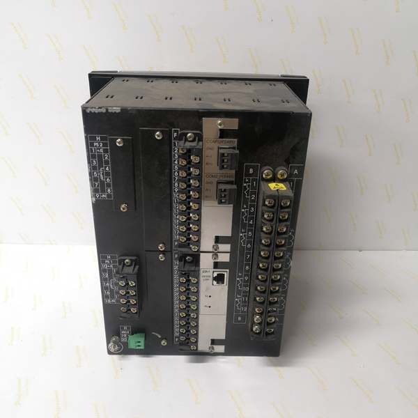
- Digital I/O:
- Slot F (F1): 16 Digital Inputs + 8 Outputs
- Slot G (G0): None (no expansion board)
- Total I/O Capacity: 16 Digital Inputs, 8 Digital Outputs
- Analog Inputs: 3-phase CT (1A/5A configurable), 3-phase VT, 1 Neutral CT, 1 Sensitive Ground CT
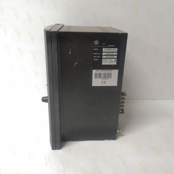
- Power Supply:
- DC: 110-250V DC (range 88-300V DC)
- AC: 120-230V AC (range 96-250V AC)
- Power Consumption: 30W (typical)
- Operating Temperature: -40°C to +70°C
- Isolation Rating: 2000V AC RMS I/O-to-chassis, 1500V RMS channel-to-channel
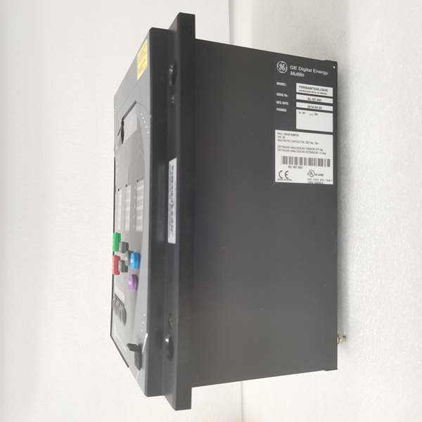
- Dimensions: 19″ rack, 6U height
- Weight: 5 kg
- Front Ports: RS232 serial port (for local configuration)
- Event Recording: Up to 512 events with 1ms time-tag resolution
- Oscillography: Up to 5 seconds capture at maximum sample rate, up to 512 records
- Trip Circuit Supervision: Not included in F1 I/O board (requires F2 board configuration)
- Language: English (language code “-” indicates English-only)

The Real-World Problem It Solves
Industrial power distribution systems require reliable protection and control of feeders, motors, and transformers with comprehensive protection functions but may not require extensive I/O expansion. The F650BABFG0HIF addresses this by integrating protection functions (overcurrent, earth fault, overvoltage, undervoltage, directional elements, auto-reclosing) into a single device with sufficient I/O capacity (16 inputs, 8 outputs) for standard feeder applications. The G0 configuration (no Slot G expansion) reduces cost and panel footprint for applications where basic I/O is adequate. Redundant RS485 and Ethernet communications ensure reliable data transmission to SCADA systems. The high-voltage power supply (110-250V DC / 120-230V AC) provides flexibility for substation and industrial plant environments where standard control voltages are available.
Where you’ll typically find it:
- 11kV-36kV distribution substations protecting outgoing feeders
- Industrial plant substations with standard air or vacuum circuit breakers
- Motor control centers requiring comprehensive motor protection
- Substation automation projects with IEC 60870-5-104 or DNP3 communication requirements
- Retrofits replacing electromechanical overcurrent relays with digital protection
Key Differentiator: The G0 (Slot G empty) configuration provides a cost-effective solution for applications requiring 16 digital inputs and 8 outputs without the need for expansion boards, making it suitable for standard feeder protection schemes with moderate I/O requirements.
Hardware Architecture & Under-the-Hood Logic
The F650BABFG0HIF is a modular digital bay controller built into a 19-inch rack, 6U height. The core components include a CPU module for processing protection algorithms and programmable logic, communication modules (redundant RS485 and 10/100BaseTX Ethernet) for data exchange, and an I/O module in Slot F providing 16 digital inputs and 8 outputs. Slot G is empty (G0 code), indicating no expansion board is installed. The basic display allows local monitoring and configuration. Power is supplied via a high-voltage input (110-250V DC or 120-230V AC).
Architecture Breakdown:
- CPU Module: 32-bit microprocessor executing protection algorithms (DFT-based phasor measurement, overcurrent, directional, distance elements) with scan cycle < 2ms for instantaneous protection
- Acquisition Modules: Digitize analog inputs from CTs and VTs at programmable sampling rates (up to 64 samples/cycle)
- Slot F I/O Module (F1): Provides 16 digital inputs for breaker status, interlocks, and control signals; 8 digital outputs for trip/close commands and alarms
- Slot G: Empty (G0) – no expansion board installed, limiting total I/O to Slot F capacity
- Communication Module 1 (Rear Serial): Dual redundant RS485 ports supporting Modbus RTU, DNP3.0, IEC 60870-5-103
- Communication Module 2 (Rear Ethernet): 10/100 Base TX Ethernet supporting Modbus TCP, IEC 60870-5-104, DNP3 over TCP
- Power Supply Module: Wide-range input (88-300V DC or 96-250V AC) with DC/DC conversion to internal voltages
- Front Panel Interface: Basic 4-line LCD display, keypad, 15 programmable LEDs, RS232 port for local configuration
- Memory Modules: Non-volatile memory for settings, event records (512 events), oscillography data (up to 512 records)
- Protection Logic Engine: Programmable logic based on IEC 61131-3 standard, configurable via EnerVista 650 Setup software
Protection Algorithm Flow:
CT/VT inputs → Analog-to-digital conversion (64 samples/cycle max) → Phasor extraction (DFT algorithm) → Protection element processing (overcurrent, directional, distance, etc.) → Programmable logic evaluation → Output decision → Trip/Close command to breaker
Communication Architecture:
The relay supports simultaneous communication on multiple ports: RS485 (dual redundant), Ethernet (10/100 Base TX), and front RS232. Protocol stack includes Modbus (RTU/TCP), DNP3.0 Level 2, IEC 60870-5-104 for SCADA integration. Time synchronization supports IRIG-B, SNTP, and IEEE 1588 PTP for precise event time tagging across multiple IEDs.
Field Service Pitfalls: What Rookies Get Wrong
Insufficient I/O Count Planning
The F650BABFG0HIF provides 16 digital inputs and 8 outputs total (all from Slot F). Rookies often assume all F650 models have the same I/O capacity and may copy panel designs from F2 or G1 configurations. With only 16 inputs available, careful allocation is required: breaker status (52a, 52b), spring-charged, local/remote selector, trip circuit healthy, close circuit healthy, interlocks, and monitoring signals can quickly consume all inputs. Running out of inputs mid-installation requires adding external interposing relays or changing the relay model.
- Field Rule: Before installation, map all required digital inputs and outputs. Allocate the 16 inputs as follows (typical feeder protection):
- 52a closed (1)
- 52b open (2)
- Spring-charged (3)
- Motor-operated (if applicable) (4)
- Trip circuit healthy (5)
- Close circuit healthy (6)
- Local/remote selector (7)
- Trip available (8)
- Close available (9)
- Protection enable (10)
- External trip (11)
- External close (12)
- Interlock 1-4 (13-16)If your scheme requires more than 16 inputs, order the G1 variant (adds 16DI+8DO in Slot G).
Missing Trip Circuit Supervision
The F1 I/O board (Slot F) provides 16 digital inputs and 8 outputs but does NOT include dedicated trip/close circuit supervision (TCS) channels. Rookies configure digital inputs for trip circuit monitoring but fail to implement proper voltage sensing across the trip coil. When a trip coil opens, the relay doesn’t detect it until a fault occurs and the breaker fails to trip.
- Quick Fix: Use two of the 16 digital inputs for trip circuit supervision:
- Configure DI5 for trip circuit supervision: Connect across trip coil with 52a contact in series, set up to detect open circuit condition
- Configure DI6 for close circuit supervision: Connect across close coil with 52b contact in series
- In EnerVista 650 Setup, enable supervision logic in the programmable scheme to alarm on loss of continuity
- Test by disconnecting trip coil wire: relay should alarm “Trip Circuit Failure” within 50ms
- Note: F1 board supervision uses general-purpose digital inputs, not dedicated TCS channels—configure supervision timing and thresholds appropriately
RS485 Bus Termination Mistakes
The redundant RS485 communication ports require proper termination at both ends of the bus. Rookies often terminate only one end or use incorrect resistor values (should be 120Ω). Signal reflections cause communication dropouts, especially when multiple relays are daisy-chained on the same RS485 bus. Symptoms include intermittent Modbus RTU or IEC 60870-5-103 failures that are difficult to diagnose.
- Field Rule: For RS485 daisy-chain installations:
- Terminate ONLY the first and last devices on the bus with 120Ω resistors
- Do NOT terminate intermediate devices
- Verify termination resistance measurement: With power off, measure between A and B lines at each terminated device—you should read 60Ω (two 120Ω resistors in parallel)
- Use shielded twisted-pair cable (Belden 3106A or equivalent) with proper grounding at one end
- Maximum cable length: 1200m at 9600 baud, reduce length proportionally at higher baud rates
- If communication issues persist, reduce baud rate or segment the bus with repeaters
Overlooking Display Language Limitation
The F650BABFG0HIF basic display is English-only (language code “-“). Rookies working in international sites may assume multilingual support is available. The relay cannot display Chinese, Spanish, French, or other languages on the basic LCD. This causes confusion for local technicians who cannot navigate menu screens or read alarms during commissioning and maintenance.
- Field Rule: For sites requiring multilingual support:
- Order the graphic display variant (M or N code) which supports multiple languages including Chinese, French, Spanish, Russian, Turkish
- If stuck with English-only display, provide laminated translation cards for common menu items
- Use EnerVista 650 Setup software for all configuration—software interface supports multiple languages
- Train local technicians on English display navigation and common alarm messages
- Critical: Never assume basic display relays support multiple languages—verify language code in order number before ordering
Power Supply Connection Errors
The HI power supply supports wide input range (88-300V DC or 96-250V AC). Rookies often connect the relay to incorrect voltage sources:
-
Connecting to 24V DC instead of 110-250V DC causes immediate power supply failure
-
Connecting to 480V AC instead of 120-230V AC damages the power module
-
Mixing AC and DC sources (e.g., connecting AC supply to DC terminals) causes catastrophic failure
-
Quick Fix: Verify power supply before connection:
- Measure source voltage with multimeter
- Confirm voltage is within rated range: 88-300V DC OR 96-250V AC (not both)
- Check terminal labeling: DC terminals are typically labeled +/−, AC terminals are labeled L/N
- For DC applications, ensure correct polarity (positive to +, negative to −)
- For AC applications, confirm phase and neutral connections
- Apply power gradually if possible (ramp up voltage using variac) to detect issues before full voltage
- After power-up, verify relay boot sequence and front panel display illumination
Ethernet Configuration Conflicts
The 10/100 Base TX Ethernet port supports static IP, DHCP, or auto-IP addressing. Rookies set static IPs that conflict with existing network devices, causing IP conflicts and communication failures. In substation LANs with multiple IEDs, improper IP assignment leads to SCADA connectivity issues.
- Field Rule: Follow network address planning:
- Obtain IP address assignment from network administrator before configuration
- Use static IP addresses for substation IEDs (avoid DHCP for reliability)
- Document IP assignments in commissioning records
- Verify no IP conflicts: ping the assigned IP before connecting the relay
- Set subnet mask, gateway, and DNS according to network design
- Configure Ethernet speed/duplex: Use auto-negotiation unless network requires fixed settings (100 Full Duplex typical)
- Test connectivity: Use EnerVista 650 Setup to ping the relay and establish communication
- For redundancy, configure both Ethernet ports (if dual-port variant) on different subnets
G0 Configuration Misunderstanding
The G0 code indicates Slot G is empty—no expansion board is installed. Rookies may attempt to add expansion boards later or assume the relay supports the same I/O capacity as G1/G4 variants. The F650BABFG0HIF cannot be field-upgraded to add Slot G expansion; the backplane may not have connectors, and firmware may not support Slot G detection.
- Field Rule: Treat G0 as a fixed configuration:
- No field-installable Slot G expansion options exist
- If future I/O expansion is anticipated, order the G1 variant initially
- If I/O expansion is required after installation, use the CIO remote I/O module via CAN bus
- Panel designs must account for the 16DI+8DO limit—no hidden expansion capability
- Verify order code (especially Slot G code) before procurement to avoid mismatch with application requirements
Commercial Availability & Pricing Note
Please note: The listed price is for reference only and is not binding. Final pricing and terms are subject to negotiation based on current market conditions and availability. The F650BABFG0HIF is based on the F650BABF1G0HI platform and is typically available with a 1-year warranty. Lead times vary by supplier and region (typically 4-8 weeks for new units). Refurbished units may be available with shorter lead times. Always verify the exact model number and configuration with the supplier before purchase, as minor variations in order code can significantly affect functionality and I/O capacity.


