
Description
Hard-Numbers: Technical Specifications
- Protection Elements: 50/51 (phase overcurrent), 50N/51N (neutral), 50G/51G (ground), 67 (directional), 21 (distance), 79 (4-shot autorecloser), 50BF (breaker failure), 27/59 (undervoltage/overvoltage), 81U/O (under/over frequency), 81R (ROCOF), 49 (thermal)
- Analog Inputs: 3-phase CT (1A/5A configurable, range 0.1-6000A), 3-phase VT (up to 208V L-N)
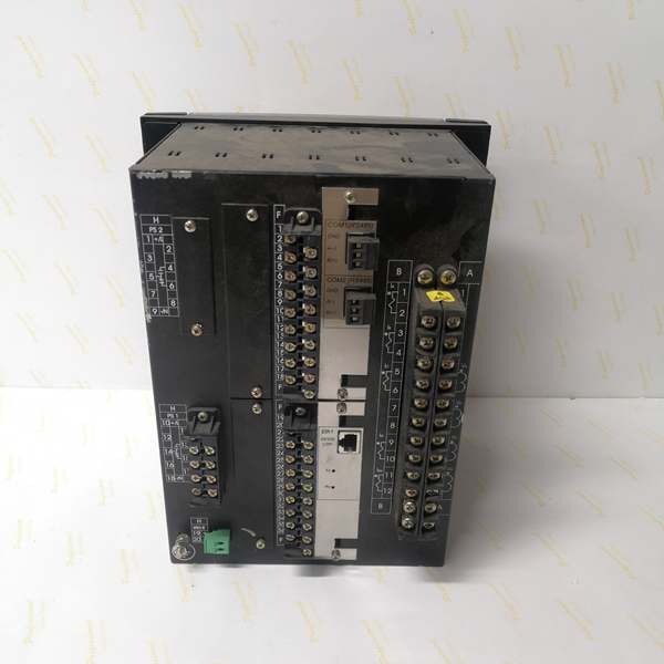
- Digital Inputs: 8 digital inputs (Slot F only, no expansion via CIO unless configured)
- Digital Outputs: 8 digital outputs (Slot F only, Form-A/Form-C/Form-SSR available)
- Trip/Close Circuit Supervision: 2 dedicated TCS channels (included in F2 board configuration)
- Communication Protocols: IEC 61850 Ed.2 (MMS, GOOSE, SV), IEC 60870-5-103/104, DNP3.0 (serial/TCP), Modbus RTU/TCP, IEEE 1588 PTP, IRIG-B, SNTP
- Ethernet Ports: 1× 10/100BaseTX (rear board B), optional 100 Base FX fiber module available in other variants
- Serial Ports: 2× RS485 (rear board A, redundant), 1× RS232 front panel
- Operating Temperature: -40°C to +70°C
- Isolation Rating: 2000V AC RMS I/O-to-chassis, 1500V RMS channel-to-channel
- Power Input: 110-250V DC (88-300V DC range) or 120-230V AC (96-250V AC range)
- Power Draw: 30W typical
- Oscillography: Up to 512 records, programmable sampling (64 samples/cycle max), up to 5 seconds capture
- Event Recorder: 479-512 events, 1ms time-tag resolution
- Trip Time: ≤20ms typical for instantaneous overcurrent
- Language Support: English-only (no language option)
- Slot G Configuration: None (G0 code—no expansion board installed)

The Real-World Problem It Solves
Standard feeder protection relays overspecify I/O capacity for simple feeder applications—16+ digital inputs and 8+ outputs when most small distribution breakers only need 6-8 inputs and 4-6 outputs. The F650BABF2GOHI strips away the Slot G expansion board (G0 code), reducing panel footprint and cost while retaining all protection functions. When a breaker fails to trip, the 50BF element detects persistent fault current and triggers adjacent breakers within 100ms—preventing cascading outages. The simplified I/O layout (8DI/8DO + 2TCS) fits basic feeder schemes without external interposing relays or complex logic configurations.
Where you’ll typically find it:
- 11kV-36kV distribution substations protecting simple outgoing feeders with minimal breaker auxiliaries
- Industrial plant substations with standard air or vacuum circuit breakers (not GIS breakers with extensive SF6 monitoring)
- Retrofits replacing electromechanical overcurrent relays where original switchgear has limited control wiring
- Cost-sensitive projects requiring full IEC 61850 capability but minimal I/O density
- Utility distribution automation deployments where standard protection schemes apply
Bottom line: Full protection capability at a lower cost—no Slot G expansion means fewer I/O points but enough for basic feeder control. Ideal when you don’t need the complexity of G1/G4/G5 expansion boards.
Hardware Architecture & Under-the-Hood Logic
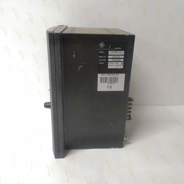
This is the same modular microprocessor-based architecture as other F650 variants, but with Slot G left empty. The CPU module handles all protection algorithms, programmable logic, and communications. The backplane uses a high-speed CAN bus to connect CT/VT acquisition modules and the Slot F I/O module. No FPGA—all signal processing runs on the 32-bit CPU with deterministic scan cycles. The “F2” code in Slot F means 8 digital inputs + 8 outputs + 2 trip/close supervision circuits. The “G0” code indicates Slot G is empty—no expansion board, limiting total I/O to what Slot F provides. The “HI” suffix indicates high-voltage power supply (110-250V DC or 120-230V AC).
- CT/VT modules isolate and digitize analog inputs (current/voltage from field transformers)
- Digitized samples stream to CPU via internal CAN bus at up to 64 samples/cycle
- CPU executes protection element algorithms (overcurrent, distance, directional) in real-time
- Programmable logic engine processes inputs from protection elements, digital contacts, and remote GOOSE messages
- Trip/control decisions routed to output relay modules with <2ms contact response time
- Oscillography engine captures pre-fault (up to 5 cycles) and post-fault data to non-volatile memory
- Communication modules push GOOSE/IEC 61850 messages to upstream SCADA via Ethernet ports
- Breaker failure element monitors fault current after trip initiation—if current persists beyond setpoint, triggers backup trip output
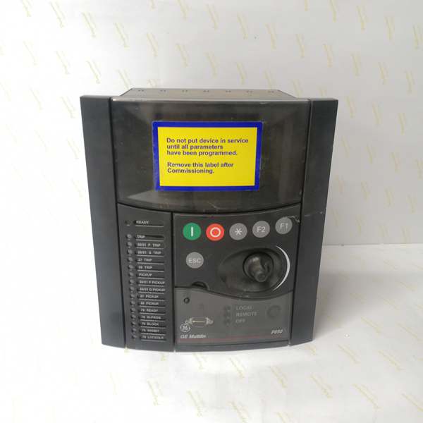
- Basic LCD display renders English-only screens for local monitoring and parameter configuration
- Critical difference: Slot G is empty (G0 code)—all I/O is handled by Slot F module only (8DI/8DO/2TCS), no expansion capability
Field Service Pitfalls: What Rookies Get Wrong
Running Out of I/O on G0 ConfigurationThe G0 code means Slot G is empty—only 8 digital inputs and 8 outputs are available (all in Slot F). Rookies wire all breaker auxiliaries (52a, 52b, spring-charged, motor-operated, SF6 low-pressure, local/remote selector, etc.) and quickly run out of input points. They’re forced to either omit critical supervision signals or add external interposing relays—defeating the purpose of choosing the cost-optimized variant.
- Field Rule: Before ordering the F650BABF2GOHI, count your breaker auxiliaries and control scheme requirements. If you need more than 8 digital inputs or 8 outputs, order the G1 variant (adds 16DI+8DO in Slot G) or consider G4/G5 expansion options. For simple vacuum breakers with basic status monitoring, 8 inputs is typically sufficient: 52a closed, 52b open, spring-charged, trip circuit healthy, close circuit healthy, local/remote, trip available, close available. If your breaker has SF6 gas monitoring or multiple position switches, you need the G1 variant.
Missed Trip/Close Circuit Supervision WiringThe F2 board includes 2 dedicated trip/close circuit supervision (TCS) inputs. Rookies connect TCS to digital input terminals instead of the supervision voltage sense points. The relay never detects an open trip coil, and when a breaker fails to trip during a fault, the operator has no warning until equipment damage occurs. With limited I/O (8DI), skipping TCS to save inputs is a rookie mistake.
- Quick Fix: Use the dedicated TCS inputs (channels 9 and 10 on the F2 board) for supervision—they don’t consume the 8 general-purpose digital inputs. Configure TCS inputs in EnerVista 650 Setup > Inputs/Outputs > Trip Circuit Supervision. Test by disconnecting the trip coil wire at the breaker—relay should alarm “Trip Circuit Failure” within 50ms. TCS supervision is mandatory for breaker failure protection—never skip it to save inputs.
Attempting to Install Slot G Expansion BoardRookies receive the F650BABF2GOHI with G0 configuration and assume they can add a Slot G board later for expansion. The relay ships with Slot G physically empty, but adding a board requires hardware modifications (backplane may not have connectors, firmware may not support Slot G detection). The upgrade path from G0 to G1 is not field-serviceable.
- Field Rule: If you anticipate future I/O expansion requirements, order the G1 variant initially rather than trying to upgrade G0 later. The cost difference is minimal compared to the replacement cost and downtime. G0 is a final configuration—no field-installable Slot G expansion options exist. If you need more I/O after installation, add a CIO remote I/O module via CAN bus instead.
Incorrect IEC 61850 IED Name with “G0” ConfusionSome engineers mistakenly configure the IEC 61850 IED name as “F650BABF2GOHI-G0” assuming the G0 is a unique identifier. The standard naming convention uses the full model number without the Slot G suffix in IED names. When SCADA systems parse the SCL file, they can’t match the IED name to the physical relay, causing GOOSE subscription failures.
- Field Rule: Configure the IEC 61850 IED name in EnerVista 650 Setup as “F650BABF2GOHI” (full model number) or a site-specific name like “Feeder3_F650”. Do not include the Slot G code in the IED name. Export the SCL file and verify the IED name matches across all subscribed IEDs. The G0 suffix is a hardware configuration indicator, not part of the logical IED identity.
Lower Digital Input Count Missed During Panel DesignPanel designers often copy I/O schedules from G1 or G4 variants, assuming all F650 models have 16+ digital inputs. The G0 configuration only has 8 digital inputs. When the panel is built and wired, technicians discover insufficient terminal blocks for the limited I/O count—wiring becomes cramped, and external terminal boards must be added retroactively.
- Quick Fix: During panel design phase, verify the Slot G configuration (G0, G1, G4, G5) and update the I/O schedule accordingly. For G0, allocate only 8 digital input terminals on the panel drawing. If external inputs are required (breaker auxiliaries beyond 8), use external terminal blocks and wire to the CIO remote I/O module if needed. Panel drawings must match the actual relay configuration—never assume all F650s have the same I/O count.
Overlooking F2 Board TCS Channel AssignmentThe F2 board provides 8 general-purpose digital inputs (DI1-DI8) plus 2 dedicated TCS channels (TCS1, TCS2). Rookies configure TCS as DI9 and DI10 in the programmable logic, treating them as general inputs. The TCS channels have different wiring requirements (voltage sensing across the trip/close coil) and applying general-purpose signals to them can damage the supervision circuit.
- Field Rule: Treat TCS1 and TCS2 as dedicated supervision channels—never use them for general-purpose breaker status or interlock signals. Configure TCS wiring according to the manual: TCS1 across trip coil with 52a contact in series, TCS2 across close coil with 52b contact in series. In EnerVista 650 Setup, configure TCS functions under “Trip Circuit Supervision” menu, not under “Digital Inputs.” TCS channels are supervised inputs with higher voltage tolerance—mixing them with general 24V/110V inputs causes configuration conflicts.
Commercial Availability & Pricing Note
Please note: The listed price is for reference only and is not binding. Final pricing and terms are subject to negotiation based on current market conditions and availability.


