
Description
Hard-Numbers: Technical Specifications
- Protection Elements: 50/51 (phase overcurrent), 50N/51N (neutral), 50G/51G (ground), 67 (directional), 21 (distance), 79 (4-shot autorecloser), 50BF (breaker failure), 27/59 (undervoltage/overvoltage), 81U/O (under/over frequency), 81R (ROCOF), 49 (thermal)
- Analog Inputs: 3-phase CT (1A/5A configurable, range 0.1-6000A), 3-phase VT (up to 208V L-N)
- Digital Inputs: Up to 80 inputs (8 standard in Slot F, expandable via CIO modules)
- Digital Outputs: Up to 56 outputs (8 standard in Slot F, Form-A/Form-C/Form-SSR available)
- Communication Protocols: IEC 61850 Ed.2 (MMS, GOOSE, SV), IEC 60870-5-103/104, DNP3.0 (serial/TCP), Modbus RTU/TCP, IEEE 1588 PTP, IRIG-B, SNTP
- Ethernet Ports: 1× 10/100BaseTX (rear board B), optional 100 Base FX fiber module available in other variants
- Serial Ports: 2× RS485 (rear board A, redundant), 1× RS232 front panel
- Front USB Port: Yes (Enhanced Display variant with direct configuration access)
- Operating Temperature: -40°C to +70°C
- Isolation Rating: 2000V AC RMS I/O-to-chassis, 1500V RMS channel-to-channel
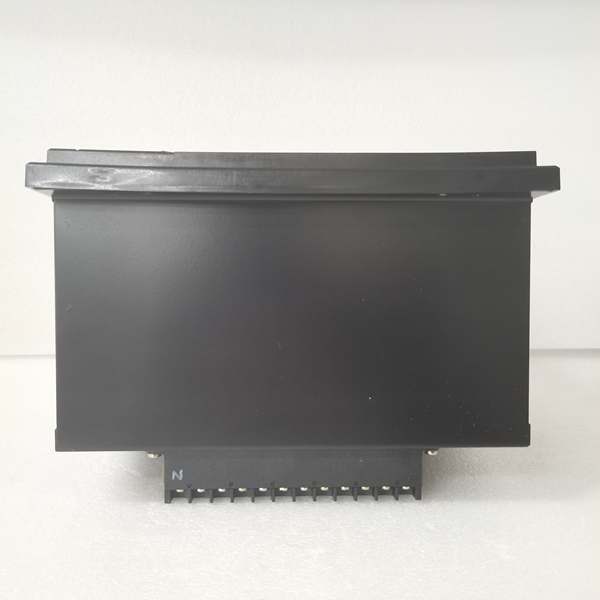
- Power Input: 110-250V DC (88-300V DC range) or 120-230V AC (96-250V AC range)
- Power Draw: 30W typical
- Oscillography: Up to 512 records, programmable sampling (64 samples/cycle max), up to 5 seconds capture
- Event Recorder: 479-512 events, 1ms time-tag resolution
- Trip Time: ≤20ms typical for instantaneous overcurrent
- Language Support: Spanish/English bilingual interface (S suffix)

The Real-World Problem It Solves
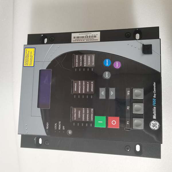
Spanish-speaking technicians in Latin American substations struggle with English-only HMIs—misinterpreting alarm messages during faults, delaying response times. The F650BABF2G1HIS eliminates language barriers with a Spanish/English bilingual display while consolidating protection, control, and metering into one chassis. The enhanced front USB port (indicated by the “S” suffix in combination with the display type) allows direct firmware upgrades and configuration downloads without opening the relay or connecting via rear RS232 ports—critical for maintaining operational security in locked substations. When a breaker fails to trip, the 50BF element detects persistent fault current and triggers adjacent breakers within 100ms, preventing cascading outages.
Where you’ll typically find it:
- 11kV-145kV distribution substations in Spanish-speaking countries (Mexico, Spain, Argentina, Colombia, Chile)
- International projects with mixed Spanish/English maintenance teams
- Industrial facilities in Latin America requiring feeder protection and bay control
- Greenfield substations in Spanish-speaking regions deploying IEC 61850 digital substations
- Retrofit projects replacing legacy electromechanical relays with bilingual modern protection
Bottom line: One relay replaces multiple legacy devices, provides Spanish/English language flexibility, enables direct USB access for maintenance, and ensures fast breaker failure backup in Spanish-language environments.
Hardware Architecture & Under-the-Hood Logic
This is a modular microprocessor-based relay where the CPU module handles all protection algorithms, programmable logic, and communications. The backplane uses a high-speed CAN bus to connect CT/VT acquisition modules, digital I/O modules, and optional remote I/O expanders (CIO modules). No dedicated FPGA—all signal processing runs on the 32-bit CPU with deterministic scan cycles. The “F2” code in Slot F means 8 digital inputs + 8 outputs + 2 trip/close supervision circuits. The “G1” code indicates Slot G has an expansion board (16 Digital Inputs + 8 Outputs), increasing total I/O capacity. The “S” suffix denotes Spanish/English language support. The enhanced display includes a front USB port for direct configuration access.
- CT/VT modules isolate and digitize analog inputs (current/voltage from field transformers)
- Digitized samples stream to CPU via internal CAN bus at up to 64 samples/cycle
- CPU executes protection element algorithms (overcurrent, distance, directional) in real-time
- Programmable logic engine processes inputs from protection elements, digital contacts, and remote GOOSE messages
- Trip/control decisions routed to output relay modules with <2ms contact response time
- Oscillography engine captures pre-fault (up to 5 cycles) and post-fault data to non-volatile memory
- Communication modules push GOOSE/IEC 61850 messages to upstream SCADA via Ethernet ports
- Breaker failure element monitors fault current after trip initiation—if current persists beyond setpoint, triggers backup trip output
- Bilingual HMI processes user inputs and displays status in Spanish/English
- Front USB port provides direct access to EnerVista 650 Setup software for configuration and firmware upgrades without rear panel connections
Field Service Pitfalls: What Rookies Get Wrong
HMI Language Reset During Firmware UpgradeUpgrading firmware without saving language settings resets the HMI to default English. Spanish-speaking technicians can’t navigate menus, delaying commissioning. The “S” suffix variant requires careful preservation of language configuration during firmware updates.
- Field Rule: Before firmware upgrade, export settings via EnerVista 650 Setup. After upgrade, re-import the settings file and verify “Language” is set to “Spanish/English” in Setpoint > Product Setup > HMI. Test by cycling through menu screens—ensure Spanish text renders correctly on all protection and metering displays.
USB Port Power Limitation for External DevicesThe front USB port is designed for configuration file transfer and firmware updates, not for powering external devices. Rookies attempt to power USB thumb drives with high power draw or charge phones, causing the relay’s USB controller to reset mid-transfer. Configuration files get corrupted, relay fails to boot after update.
- Quick Fix: Use only standard USB thumb drives with low power consumption (<500mA). Avoid external USB hubs or powered devices. If firmware update fails mid-transfer, power cycle the relay and retry. Keep a backup of configuration files on multiple drives. The USB port uses USB 2.0 specification with standard 500mA current limit—respect this.
Slot G Expansion Board Not RecognizedThe “G1” code means Slot G contains an expansion board (16DI + 8DO). Rookies install the relay but forget to configure the expansion board in EnerVista 650 Setup. The extra I/O points don’t appear in the digital input/output menus, forcing them to add external interposing relays for signals that should have been handled internally.
- Field Rule: After hardware installation, access EnerVista 650 Setup > System Info > Hardware Configuration and verify Slot G shows “16 Digital Inputs + 8 Outputs.” Configure the expansion board inputs/outputs in the Inputs/Outputs menu. Test by applying voltage to the expansion board inputs and verifying status changes on the HMI Actual Values screen.
Spanish Language Translation InconsistenciesSome protection function names in Spanish display don’t match local terminology. Rookies unfamiliar with Spanish electrical terms misinterpret alarm messages. For example, “Falla de Disyuntor” (Breaker Failure) might be confusing to technicians accustomed to “Fallo de Interruptor” terminology.
- Quick Fix: Create a translation cheat sheet for common alarm messages in Spanish versus local terminology. Train technicians on standard Spanish electrical terms used in GE firmware. If critical, configure alarm annunciation outputs to external annunciator panels with bilingual labels. The Spanish language option follows IEC 60870-5-103 terminology standards—reference the Spanish translation guide in the manual.
USB Firmware Update Without External Ground ReferenceUpdating firmware via front USB while the relay is ungrounded can cause ESD damage to the USB controller. Rookies disconnect the relay ground for maintenance and then plug in the USB drive, risking static discharge. The USB port fails after several updates, requiring relay replacement.
- Field Rule: Always maintain proper substation ground connection during USB operations. If the relay must be ungrounded for maintenance, use an anti-static wrist strap connected to the substation ground, or plug the USB drive into a grounded laptop first, then connect to the relay. Avoid working in low-humidity environments without ESD protection. The USB port is not isolated—ground integrity is critical during file transfers.
Missing GOOSE Subscription After Firmware UpgradeThe “S” suffix variant with enhanced display includes IEC 61850 Edition 2 support. After firmware upgrade, GOOSE control block names change. Rookies don’t update the SCL file in downstream IEDs, causing message subscription failures. Spanish-language SCADA operators see “GOOSE Lost” alarms but can’t identify which IED is affected due to language confusion.
- Field Rule: After any firmware upgrade on the F650BABF2G1HIS, export the new SCL file and re-import it into all subscribed IEDs. Verify GOOSE subscriptions using the IEC 61850 configuration tool. Update any bilingual alarm displays in SCADA to match the new GOOSE message identifiers. Test GOOSE message flow using the IEC 61850 test client before returning the bay to service.
Commercial Availability & Pricing Note
Please note: The listed price is for reference only and is not binding. Final pricing and terms are subject to negotiation based on current market conditions and availability.


