
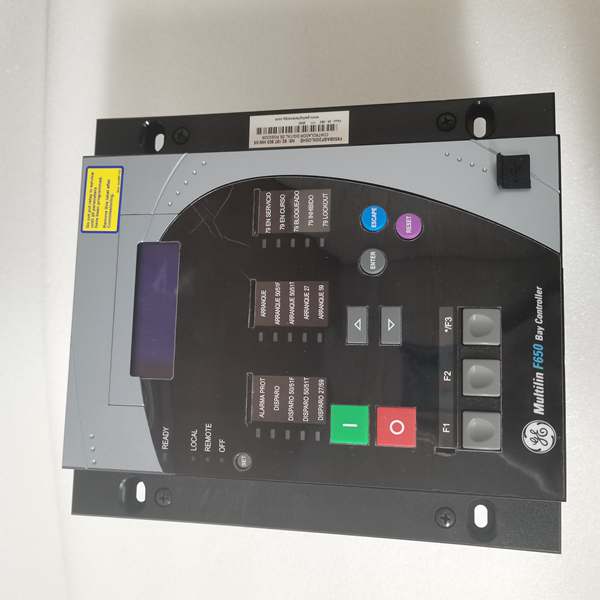
Description
Hard-Numbers: Technical Specifications
- Protection Elements: 50/51 (phase overcurrent), 50N/51N (neutral), 50G/51G (ground), 67 (directional), 21 (distance), 79 (4-shot autorecloser), 50BF (breaker failure), 27/59 (undervoltage/overvoltage), 81U/O (under/over frequency), 81R (ROCOF), 49 (thermal)
- Analog Inputs: 3-phase CT (1A/5A configurable, range 0.1-6000A), 3-phase VT (up to 208V L-N)
- Digital Inputs: Up to 80 inputs (depending on CIO module configuration)
- Digital Outputs: Up to 56 outputs (Form-A, Form-C, SSR available)
- Communication Protocols: IEC 61850 Ed.2 (MMS, GOOSE, SV), IEC 60870-5-103/104, DNP3.0 (serial/TCP), Modbus RTU/TCP, IEEE 1588 PTP, IRIG-B, SNTP
- Ethernet Ports: 1× 10/100BaseTX (with optional redundant fiber or dual TX options K/M/N)
- Serial Ports: 2× RS485 (rear), 1× RS232 front panel
- Operating Temperature: -40°C to +70°C
- Isolation Rating: 2000V AC RMS I/O-to-chassis, 1500V RMS channel-to-channel
- Power Input: 110-250V DC (88-300V DC range) or 120-230V AC (96-250V AC range)
- Power Draw: 30W typical
- Oscillography: Up to 512 records, programmable sampling (64 samples/cycle max), up to 5 seconds capture
- Event Recorder: 479-512 events, 1ms time-tag resolution
- Trip Time: ≤20ms typical for instantaneous overcurrent
- Language Support: Chinese/English bilingual display (C suffix configuration)

The Real-World Problem It Solves
Legacy feeder protection requires stacking multiple single-function relays—overcurrent here, distance there, separate autorecloser box. The F650BABF1G0HIC consolidates protection, control, metering, and breaker monitoring into one chassis, eliminating inter-relay wiring nightmares and reducing panel footprint in space-constrained HV switchgear cubicles. When a breaker fails to open (stuck mechanism), the 50BF element detects the fault current persisting and trips adjacent breakers within 100ms—preventing cascading busbar collapse. The bilingual HMI (Chinese/English) simplifies local operation for multi-lingual crews in international projects.
Where you’ll typically find it:
- 11kV-145kV distribution substations protecting outgoing feeders and transformer bays
- Industrial power plants requiring breaker failure protection and four-shot reclosing for overhead lines
- Utilities upgrading from electromechanical to numerical protection with IEC 61850 process bus integration
- International projects requiring Chinese/English bilingual operator interface
Bottom line: One relay replaces racks of old-school relays, provides high-speed breaker failure backup, and integrates directly into digital substations without copper wiring for inter-tripping. Bilingual HMI eliminates translation delays during fault response.
Hardware Architecture & Under-the-Hood Logic
This is a modular microprocessor-based relay where the CPU module handles all protection algorithms, programmable logic (FlexLogic-equivalent), and communications. The backplane uses a high-speed CAN bus to connect CT/VT acquisition modules, digital I/O modules, and optional remote I/O expanders. No dedicated FPGA—all signal processing runs on the 32-bit CPU with deterministic scan cycles. Redundant power supplies (if configured) share the 50% load each and hot-swap without CPU reset. The C suffix configuration enables Chinese/English language selection on the front-panel display and HMI screens.
- CT/VT modules isolate and digitize analog inputs (current/voltage from field transformers)
- Digitized samples stream to CPU via internal CAN bus at up to 64 samples/cycle
- CPU executes protection element algorithms (overcurrent, distance, directional) in real-time
- Programmable logic engine processes inputs from protection elements, digital contacts, and remote GOOSE messages
- Trip/control decisions routed to output relay modules with <2ms contact response time
- Oscillography engine captures pre-fault (up to 5 cycles) and post-fault data to non-volatile memory
- Communication modules push GOOSE/IEC 61850 messages to upstream SCADA via Ethernet ports
- Breaker failure element monitors fault current after trip initiation—if current persists beyond setpoint, triggers backup trip output
- HMI display renders bilingual screens (Chinese/English) based on operator language selection
Field Service Pitfalls: What Rookies Get Wrong
CT Polarity Mismatch on Directional ElementsWiring the CT secondary polarity reversed on the 50/67 directional overcurrent element causes the relay to see forward faults as reverse. The relay blocks tripping when it should operate—fault stays on the system until backup protection clears it (too slow, equipment damage). Bilingual display may show polarity errors in Chinese or English—know your symbols.
- Field Rule: Commission directional protection with primary load current flowing. Verify CT secondary phase angle at relay terminals using a phase meter—all phases should be within ±5° of reference. If one phase shows 180° shift, swap polarity at CT or relay terminals before enabling the trip output. Confirm polarity verification results on both language screens.
Breaker Failure (50BF) Initiate Signal Not WiredThe breaker failure function needs an external initiate signal (usually from the protection trip output). Rookie engineers connect the 50BF initiate to the wrong contact or forget it entirely. When a breaker jams, the 50BF never sees the trip command and fails to trip adjacent breakers—fault spreads to the entire busbar.
- Quick Fix: Configure the 50BF Initiate input in EnerVista 650 Setup to receive the protection trip output signal (usually contact output #1). Verify the signal path with a secondary injection test: inject fault current, confirm protection trips, then verify 50BF initiate activates on the Actual Values screen. If not, reconfigure the initiate signal source.
RS485 Network Without Bias ResistorsWiring the Modbus RTU or DNP3 RS485 ports in a multidrop network without 120Ω termination at both ends. The network works with two devices but fails with three or more—random communication alarms, SCADA loses visibility. Rookies blame the relay, but it’s a cabling issue.
- Field Rule: Install 120Ω termination resistors across the A and B lines at the physical first and last devices on the RS485 bus. For networks longer than 1000 meters, add bias resistors (560Ω to VCC, 560Ω to GND) to maintain logic levels when the bus is idle. Verify signal integrity with an oscilloscope—clean square waves on A/B lines.
Ignoring Trip Circuit Supervision (TCS) WiringThe F650 has dedicated TCS inputs to monitor breaker trip coil continuity. Rookies leave these inputs unwired or connected to the wrong supervision contacts. When the trip coil opens (broken wire, blown fuse), the relay never knows—next fault occurs, breaker won’t trip, equipment gets fried.
- Field Rule: Connect TCS supervision inputs across the breaker trip coil (52a contact in series with the supervision circuit). Test by disconnecting the trip coil wire at the breaker—the relay should alarm “Trip Circuit Failure” within 50ms. If no alarm, check TCS input wiring and supervision settings in EnerVista. Verify alarm message displays correctly in both languages.
Firmware Upgrade Forgetting IEC 61850 SCL Re-importUpgrading F650 firmware changes GOOSE control block addresses and SCL file structure. The downstream IEDs (distance relays, busbar protection) still subscribe to the old APPIDs. After a fault, critical GOOSE messages never arrive—backup schemes fail to operate.
- Field Rule: After any firmware upgrade, export the new SCL file from the upgraded F650 and re-import it into all subscribed IEDs. Verify GOOSE subscriptions using the IEC 61850 configuration tool. Never assume backward compatibility—always revalidate the complete GOOSE message mapping before returning the bay to service.
Bilingual Display Language Lock After Factory ResetPerforming a factory reset on the C-suffix model can lock the display to English-only until language is reconfigured. Operators expecting Chinese menus get confused during startup—commissioning delays while navigating unfamiliar English screens.
- Quick Fix: After any firmware upgrade or factory reset, immediately access “Setpoint > Product Setup > Language Settings” and select “Chinese/English” bilingual mode. Test by cycling through HMI screens—verify both languages appear correctly. Save the configuration to prevent language loss during power cycles.
Commercial Availability & Pricing Note
Please note: The listed price is for reference only and is not binding. Final pricing and terms are subject to negotiation based on current market conditions and availability.


