

Description
Hard-Numbers: Technical Specifications
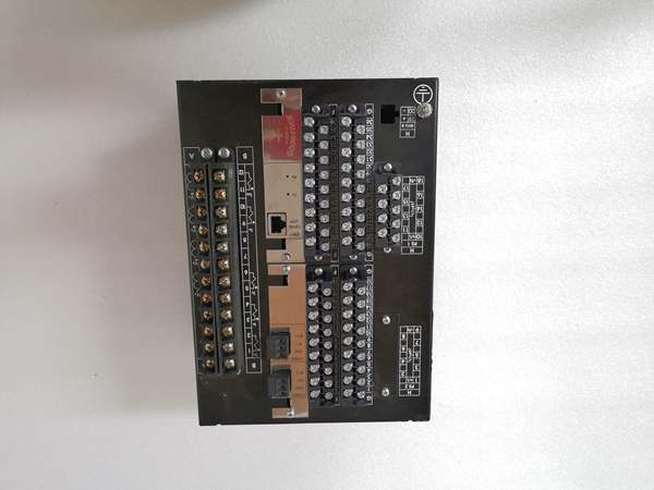
- Analog Inputs: 5 current (IA, IB, IC, IN, IRES) + 4 voltage (VA, VB, VC, VX)
- Digital Inputs: 16 configurable inputs (opto-isolated, 24-48VDC/AC nominal)
- Digital Outputs: 16 Form-C contacts (6A continuous @ 30VDC, 250VAC)
- Input Current Range: 0.1-10A (adjustable ratios via software)
- Input Voltage Range: 10-277V L-L or 10-160V L-N (adjustable ratios)
- Protection Functions: Overcurrent (50/51), Ground (50N/51N/50G/51G), Directional (67P/67N/67G), Frequency (81), Voltage (27/59), Breaker Failure (50BF), Autoreclose (79), Synchrocheck (25)
- Communication Protocols: IEC 61850 Edition 2, IEC 60870-5-103/104, Modbus TCP/IP, DNP3, PRP/HSR (IEC 62439)
- Ethernet Ports: Rear board with Option G provides 2×10/100/1000BASE-T ports + 1×SFP slot
- Time Synchronization: IEEE 1588 (PTP), IRIG-B, SNTP with dual master support
- Recording Capacity: 479 time-tagged events (1ms resolution), 5 seconds oscillography at max sample rate, fault location with 0.1% accuracy
- Operating Temperature: -40°C to +70°C (-40°F to +158°F)
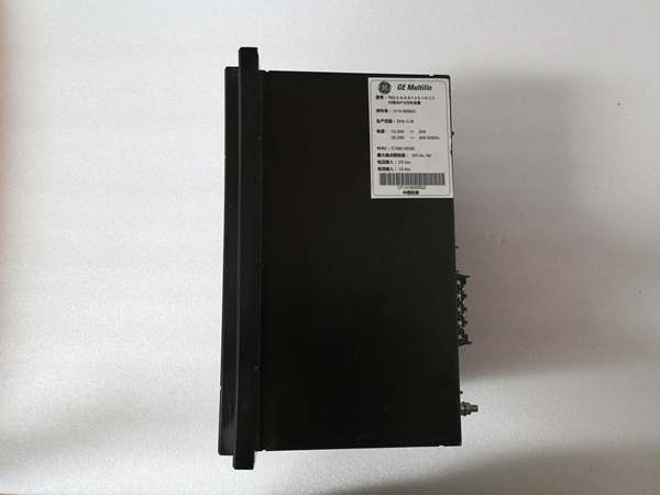
- Power Supply: 24VDC ±20% (Option HI indicates redundant power supply)
- Power Draw: 20-25W typical with full I/O load
- Dimensions: 19″ rack mount, 6U height (approx. 266mm), 3.5U depth (approx. 154mm)
- Weight: 0.8 kg

The Real-World Problem It Solves
This relay eliminates the nightmare of coordinating multiple protection devices for feeder circuits by consolidating overcurrent, ground, directional, frequency, and voltage protection into a single intelligent bay controller. Its integrated metering, oscillography, and fault recording capabilities give you the forensic data needed to troubleshoot faults without dragging oscilloscopes and recorders into the field, while its redundant communications architecture keeps your SCADA system online even when one network path fails.
Where you’ll typically find it:
- Distribution substations protecting radial feeders serving industrial parks or commercial districts
- Wind farm and solar plant interconnect points with anti-islanding and DG protection requirements
- Industrial plant main incoming feeders requiring breaker failure, autoreclosing, and load shedding schemes
Bottom line: It’s your single-point solution for feeder protection that combines the brains of a protection relay with the muscle of a bay controller—all while keeping the substation operator informed and connected.
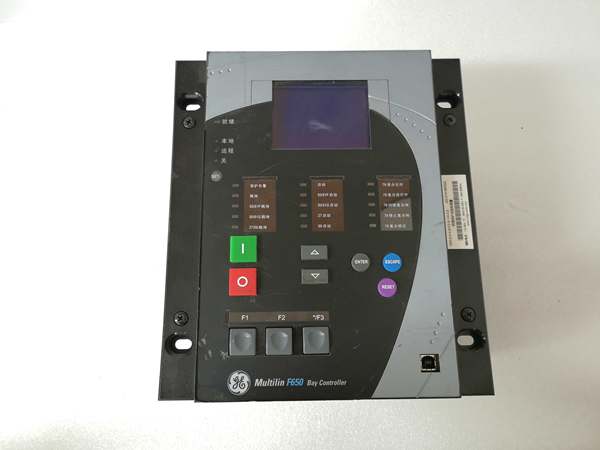
Hardware Architecture & Under-the-Hood Logic
The F650-N-F is a modular 19″ rack-mount device comprising a power supply, CPU, I/O modules, and communication boards. The Option G rear Ethernet board provides dual copper ports with SFP fiber capability, while the Option HI configuration includes redundant power supplies for mission-critical applications. The relay uses a dedicated DSP-based measurement subsystem for high-speed sampling of analog inputs and a separate RISC processor for protection logic and communication handling.
Signal and protection flow breakdown:
- Current and voltage signals from CTs/VTs pass through anti-aliasing filters and are digitized by ADCs at programmable rates (up to 64 samples/cycle)
- DSP calculates phasors, sequence components (positive, negative, zero sequence), and harmonics using DFT algorithms
- Protection elements compare calculated values against setpoints—50/51 elements check magnitude, 67 elements evaluate directional vectors using polarizing quantities
- Programmable logic engine (F650 Logic Configuration) processes protection outputs, interlocks, and control schemes using Boolean logic and timers
- Trip decisions trigger output contact drivers through isolation circuits while simultaneously initiating event recording
- Oscillography module captures pre-fault (typically 5 cycles) and post-fault waveforms in non-volatile memory
- Communication board formats data for protocols (IEC 61850 mapping, Modbus registers, DNP3 objects) and transmits via dual Ethernet ports with PRP/HSR redundancy
- Faceplate HMI drives LCD display with menu navigation, status indicators, and rotary shuttle key for local control
Field Service Pitfalls: What Rookies Get Wrong
Missing the bootcode/firmware compatibility matrixThis is the number one cause of bricked F650s. Techs upgrade firmware to 8.53 without checking the bootcode version, and the relay won’t boot after power cycle. The firmware 8.52+ only works with bootcode 2.35, and firmware 8.53+ requires new CPU hardware with Rear Ethernet Board options G, H, J, K, L, or M.
- Field Rule: Check current bootcode and firmware on the main screen (displayed after “F650” text) before any upgrade. Download the compatibility matrix from GE’s firmware release notes. Never upgrade firmware below version 7.0x to 8.53+—you need a new relay for that jump.
Ignoring the I2t breaker maintenance counterThe F650 tracks breaker contact wear using accumulated I²t values, but rookie engineers never look at this setting. The counter reaches 9999.99 KA²s and trips the alarm, but nobody knows what it means until a breaker fails to interrupt fault current.
- Field Rule: Configure breaker maintenance settings at System Setup > Breaker. Set the Maximum (KI²t) value according to the breaker manufacturer’s interrupt rating sheet. Check this counter during annual maintenance and reset after breaker overhauls. If it hits the alarm, schedule breaker contact replacement immediately.
Wiring 67 directional elements without correct CT polarityDirectional protection fails silently when the CT polarity doesn’t match the relay’s MTA (Maximum Torque Angle) setting. The relay runs in reverse direction, and during faults it blocks tripping when it should operate—or trips unnecessarily.
- Field Rule: Perform a primary injection test on each directional element (67P, 67N, 67G). Apply known fault currents and verify the relay correctly identifies FORWARD vs REVERSE. Check the MTA setting matches your system impedance angle. Never rely solely on secondary injection—test with actual CT ratios if possible.
Neglecting trip circuit supervision (TCS)Some techs wire TCS inputs incorrectly or disable them entirely, thinking it’s an unnecessary nuisance. Then when the trip coil opens or the battery circuit fails, you don’t know until the breaker refuses to trip during a fault.
- Field Rule: Enable TCS in Protection Elements menu. Wire supervision per the manual’s single-line diagram. The relay will issue an alarm if the trip circuit continuity is lost, giving you time to fix it before a real fault occurs.
Forgetting PRP/HSR redundancy configurationThe Option G Ethernet board supports Parallel Redundancy Protocol and High-availability Seamless Ring, but rookie engineers just plug in both cables and assume redundancy works automatically. Without proper VLAN tagging and MAC address duplication in the switch, both ports contend on the network.
- Field Rule: Configure PRP/HSR in Communication Settings menu. Ensure your network switches support the chosen protocol. Use different VLANs for each redundant path if you’re sharing infrastructure. Test redundancy by unplugging one cable—SCADA should stay online with zero packet loss.
Please note: The listed price is for reference only and is not binding. Final pricing and terms are subject to negotiation based on current market conditions and availability.


