
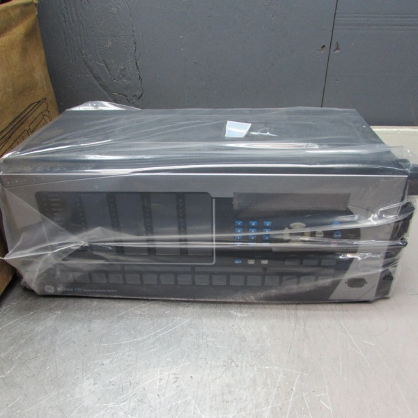
Description
Hard-Numbers: Technical Specifications
- Feeder Capacity: Up to 6 feeders (5 with busbar voltage measurement)
- Protection Elements: 87/87L differential, 50/51 phase/ground overcurrent, 21 distance, 59/27 voltage, 81 frequency, 79 recloser (up to 4 shots)
- Analog Inputs: Multi-channel CT/VT (1A/5A CT rated), supports IEC 61850-9-2LE, IEC 61869 process bus
- Digital I/O: Up to 80 inputs, up to 56 outputs (Form-A, Form-C, SSR, latching types available)
- Communication Protocols: IEC 61850 Ed.1/Ed.2 (MMS, GOOSE, SV), DNP3.0 (serial/TCP), Modbus RTU/TCP, IEC 60870-5-103/104, IEEE 1588 PTP
- Ethernet Ports: 3 independent 100Mbps ports (redundancy via IEC 62439-3 PRP/HSR)
- Oscillography: 64 records, 64 samples/cycle, up to 40 analog + 64 digital channels
- Event Recorder: 1024 events, 1µs time-tag resolution
- Operating Temperature: -40°C to +70°C
- Storage Temperature: -40°C to +85°C
- Humidity: 5% to 95% non-condensing
- Power Input: 24/48/110/220V DC or AC (depends on power module)
- Power Draw: 15W typical (varies with module configuration)
- Isolation Rating: 2000V AC RMS I/O-to-chassis, 1500V RMS channel-to-channel
- Weight: Approx. 3.5 kg (varies with module count)
- Mounting: Panel-mount (flush or surface), 19-inch rack option

F35N03HUH8LH6AM6EW7C
The Real-World Problem It Solves
Multiple feeders without centralized protection mean you need individual relays, wiring mess, and coordination headaches. This unit handles up to six feeders in one box—differential, overcurrent, distance, reclosing—all while talking IEC 61850 to the rest of the substation. One chassis replaces racks of single-function relays, cuts copper wiring, and gives you a single pane of glass for protection, metering, and event recording.
Where you’ll typically find it:
- Distribution substations protecting multiple outgoing feeders
- Industrial plants with complex feeder arrangements needing coordinated protection
- Retrofits where panel space is limited but functionality demands have increased
Bottom line: One relay, multiple feeders, reduced wiring footprint, and full IEC 61850 integration.
Hardware Architecture & Under-the-Hood Logic
This is a modular UR-series relay with a CPU module handling protection algorithms, FlexLogic programmable control, and communications. The backplane accepts CT/VT modules for analog acquisition, digital I/O modules for contact inputs and outputs, and optional process bus modules for IEC 61850-9-2 Sampled Values. No dedicated FPGA—protection runs on the CPU with deterministic scan cycle (typically 1-2ms). The architecture is object-oriented software running on this hardware, where protection functions are instantiated as independent objects.
- CT/VT modules accept 1A/5A current and voltage signals from field transformers
- Analog signals are conditioned, isolated, and digitized by ADCs on CT/VT modules
- Digitized samples are passed to CPU module via backplane
- CPU runs protection element algorithms (differential, overcurrent, distance) on sampled data
- FlexLogic equations combine protection element outputs with digital inputs to form trip/control decisions
- Digital I/O modules convert CPU output commands to physical contact closures for breaker control
- Process bus module (if equipped) publishes Sampled Values over IEC 61850-9-2LE/IEC 61869
- CPU processes GOOSE messages for inter-relay communications and interlocking
- Event recorder, oscillography, and data logger capture fault data to non-volatile memory
- Ethernet ports handle IEC 61850, DNP3, Modbus, and file transfers to SCADA/HMI
F35N03HUH8LH6AM6EW7C
Field Service Pitfalls: What Rookies Get Wrong
CT Polarity Reversed on Differential InputsConnecting the CT secondary with reversed polarity on one feeder’s differential input. The differential element sums currents with a 180° phase error—resulting in false differential current during normal load. The relay trips on a phantom internal fault, taking down a healthy feeder.
- Field Rule: Commission differential protection with primary load current flowing. Measure secondary current magnitude and phase at the relay terminals using a phase meter. Verify all feeder CTs are in-phase with the reference. If one CT shows 180° shift, swap the polarity at the CT or at the relay terminals before enabling the trip.
GOOSE Subscription Mismatch After Firmware UpgradeUpgrading the relay firmware from v7.6x to v7.8x changes the default GOOSE control block addressing. Your downstream relay is still subscribed to the old APPID and doesn’t receive trip commands. A fault occurs, and the upstream relay trips—but the downstream breaker stays closed.
- Field Rule: After any firmware upgrade, export the SCL file from the upgraded relay and re-import it into all subscribed IEDs. Verify GOOSE subscriptions using the IEC 61850 configuration tool. Never assume backward compatibility for GOOSE APPIDs—always re-validate subscriptions after firmware changes.
Ignoring Process Bus Sample Rate ConfigurationConfiguring the process bus module for 80 samples/cycle when the merging unit only supports 48 samples/cycle. The relay reports “SV Invalid” and doesn’t use the sampled values, falling back to last-known-good analog inputs. Protection degrades or becomes blind during a fault.
- Field Rule: Match the Sampled Values (SV) sample rate in the relay to the merging unit’s configured rate. For IEC 61850-9-2LE, typical rates are 80 or 48 samples/cycle at 50/60Hz. Check the merging unit settings first, then configure the relay’s process bus module accordingly. Verify SV reception via the relay’s monitoring display—look for “SV Valid” indicator before enabling protection.
Flexible I/O Module Not Seated ProperlyThe high-density I/O module (up to 120 inputs/72 outputs) doesn’t engage the backplane pins fully. The last 8 digital inputs never register status changes. A breaker position monitoring input on channel 112 is stuck at “Open”—the relay thinks the breaker is closed when it’s actually open.
- Field Rule: High-density modules have more pins and tighter clearance. Insert the module at an angle, then rock it down gently until both locking screws engage. Verify the module is seated by checking the front panel status LEDs—most I/O modules have a “Module OK” LED. If it’s off or flashing, reseat the module.
Using Modbus RTU Over RS485 Without Bias ResistorsWiring the Modbus RTU RS485 port to a multi-drop network without 120Ω termination resistors at both ends. The network works with one device but fails with three or more. The relay reports communication errors, and SCADA can’t read metered values or event logs.
- Field Rule: RS485 networks need 120Ω termination resistors at both physical ends of the bus. Install them across the A and B lines at the first and last devices. For networks longer than 1000 meters, add bias resistors (typically 560Ω to VCC, 560Ω to GND) to maintain proper logic levels when the bus is idle.
Commercial Availability & Pricing Note
Please note: The listed price is for reference only and is not binding. Final pricing and terms are subject to negotiation based on current market conditions and availability.


