
Description
Hard-Numbers: Technical Specifications
- Analog Input Channels: 6 isolated (configurable for 4-20mA / 0-10V / TC / RTD)
- Input Ranges: 4-20mA, 0-10V DC, ±10V DC, thermocouple, RTD 100Ω Pt
- Isolation: Optoisolators, 1500V RMS channel-to-chassis
- Output Channels: 6 scaled analog outputs to backplane
- Gain/Offset: Per-channel programmable via jumpers or pots
- Bandwidth (–3dB): DC to 500 Hz per channel
- Accuracy: ±0.25% FS at 25°C
- Common-Mode Rejection: 80 dB @ 60 Hz
- Temperature Coefficient: ±50 ppm/°C
- Operating Temperature: –35°C to +70°C
- Storage Temperature: –40°C to +85°C
- Humidity: 5% to 95% non-condensing
- Power Input: 125V DC ±10%
- Power Consumption: 8W typical
- LED Indicators: 6 red (channel status), 1 amber (power/health)
- Test Points: 12 TP access points (input/output per channel)
- Jumpers: 4 configuration jumpers (input type, range selection)
- Weight: 0.7 kg (1.5 lbs)
- Mounting: Backplane via edge connector
- Compatible Controllers: Mark IV Speedtronic

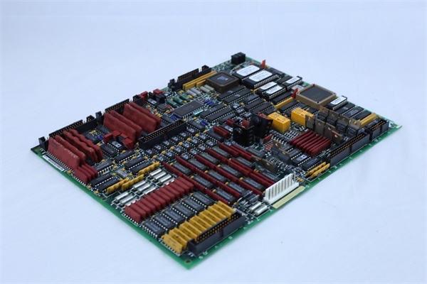
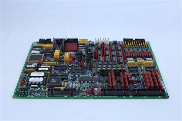
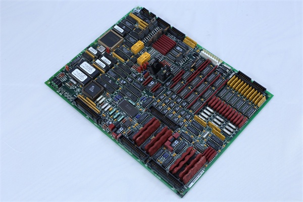
GE DS200TCQAG1B
The Real-World Problem It Solves
Field sensors produce low-level analog signals that degrade over long cable runs and get corrupted by plant EMI. Without proper conditioning, the controller sees noisy, scaled-wrong inputs, leading to poor load control, instability, and nuisance trips. This board amplifies, isolates, and scales these signals so the Mark IV gets clean, usable measurements—protecting your load control loop accuracy and stability.
Where you’ll typically find it:
- Mark IV turbine load control cabinets receiving fuel valve position feedback
- Steam turbine load sensor interface for governor control
- Gas turbine exhaust temperature signal conditioning
- Field RTD and thermocouple interface for bearing temperature monitoring
Bottom line: Clean, isolated analog inputs mean accurate load control and fewer false trips.
Hardware Architecture & Under-the-Hood Logic
This is a multi-channel analog interface board with per-channel signal conditioning, isolation, and scaling. No CPU—signal path is fully analog with jumpers selecting input types and ranges. Each channel has its own amplifier, isolation, and output stage.
- Field signals (4-20mA/0-10V/TC/RTD) enter via terminal block
- Input selection jumpers configure each channel for input type
- Per-channel instrumentation amplifiers scale and filter signals
- Active filters remove EMI; cut-off ~500 Hz per channel
- Optoisolators provide galvanic isolation (1500V RMS)
- Output amplifiers drive scaled signals to backplane
- Gain/offset trim pots fine-tune per-channel scaling
- LED indicators show channel status (red=normal, off=loss-of-signal)
- Amber health LED indicates board power and general health
- Test points provide access to pre/post-isolation signals for troubleshooting
GE DS200TCQAG1B
Field Service Pitfalls: What Rookies Get Wrong
-
Incorrect jumper configuration for input typeSetting jumpers for 4-20mA when the field device is 0-10V. The board sees a saturated input and outputs full scale. The controller thinks load is at 100%, and fuel commands go to minimum—turbine swings.Field Rule: Verify field device output before configuring jumpers. For 4-20mA, use current input jumper; for 0-10V, use voltage input jumper. Always re-check after any device replacement.
-
Ground loops through shared signal returnsSharing sensor return wiring between multiple boards. The ground potential difference causes 50/60 Hz hum on the analog inputs. The controller sees noise and hunts, causing governor oscillation.Quick Fix: Keep each sensor return isolated to its own board. Use twisted shielded pairs with the shield grounded at one point only—preferably the cabinet ground. Check for voltage between returns—if >0.5V, you have a ground loop.
-
Ignoring the amber health LED after power-upAmber LED doesn’t light after rack power is applied. Techs assume the board is fine and move on. The health LED indicates board power supply failure—one of the DC-DC converters is down. Channels won’t amplify, and the controller defaults to last-good or failsafe.Field Rule: If amber health is off, verify 125V DC at the connector. Measure DC output voltages on the board power test points. No 5V or 15V? Replace the board—do not attempt onboard power repair in the field.
-
Calibrating gain/offset without reference sourceAdjusting trim pots using only the field signal as reference. If the field sensor is out of spec, you’re calibrating to a wrong value. The board works fine, but the controller sees wrong load values.Field Rule: For gain/offset calibration, use a calibrated reference source (e.g., 12.00mA for 50% of 4-20mA). Set input, then adjust trim pot for expected output (e.g., 5.00V on output test point). Document per-channel calibration values.
-
Overlooking RTD lead resistance compensationUsing 2-wire RTDs for long runs and not compensating for lead resistance. The board sees extra resistance and reads high. Bearing temps look elevated, and you trip on false high-temp alarms.Field Rule: For RTD inputs, use 3-wire or 4-wire connections when possible. If stuck with 2-wire, measure lead resistance and subtract it from the reading. For critical bearings, run a new 3-wire lead.
Commercial Availability & Pricing Note
The listed price is for reference only and is not binding. Final pricing and terms are subject to negotiation based on current market conditions and availability.


