
Description
Hard-Numbers: Technical Specifications
- Firing Channels: 12 independent thyristor firing outputs
- Pulse Width: Adjustable 10-120° electrical angle
- Pulse Amplitude: 15V @ 500mA per channel
- Firing Resolution: 0.1° electrical angle
- Timing Accuracy: ±0.5° at 60Hz
- Crystal Oscillator: 11.000 MHz
- Operating Temp: -35°C to +70°C
- LED Indicators: 14 red + 1 amber status LEDs
- Test Points: 29 TP access points
- Jumpers: 2 configuration jumpers
- Power Draw: 15W @ 125V DC
- Weight: 0.91 kg (2.0 lbs)
- Mounting: Backplane via edge connector
- Compatible Controllers: Mark IV Speedtronic
- Revision: 1J1C (enhanced timing stability)

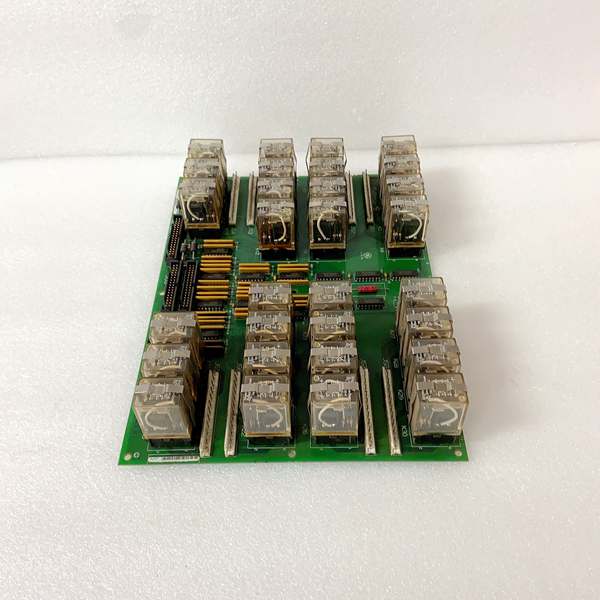
GE DS200TCRAG1ACC
The Real-World Problem It Solves
Thyristor banks need precise firing pulses to convert AC to DC or control frequency. If firing timing drifts by even 2-3°, you get ripple on the DC bus, harmonic distortion on the grid, and worst case—thyristor destruction from uneven current sharing. This board generates 12 synchronized firing pulses with microsecond accuracy, keeping your excitation system clean and stable.
Where you’ll typically find it:
- Mark IV excitation system static exciter firing control
- Static frequency converters for motor-driven start applications
- DC motor drive SCR banks in steel mill applications
- Large battery charger SCR control systems
Bottom line: Precise thyristor firing timing—when you’re switching thousands of amps at 480V AC, timing errors destroy components.
Hardware Architecture & Under-the-Hood Logic
This is a dedicated firing pulse generator with crystal-stabilized timing and digital counter logic. No CPU—firing timing is generated by hardware counters triggered from the crystal oscillator. The board accepts auxiliary daughter cards for expanded functionality.
- 11MHz crystal oscillator provides master timing reference
- Line synchronization circuit locks to incoming AC line frequency
- Phase-locked loop (PLL) adjusts firing timing to line zero-crossing
- 12-bit counters generate firing angles for each thyristor channel
- Pulse width modulators set output pulse duration
- Output driver stages amplify pulses to 15V @ 500mA
- Optoisolators provide galvanic isolation between control and firing outputs
- 8-bit static MOS RAM stores firing angle and pulse width parameters
- 4-bit up/down counters handle sequential firing sequencing
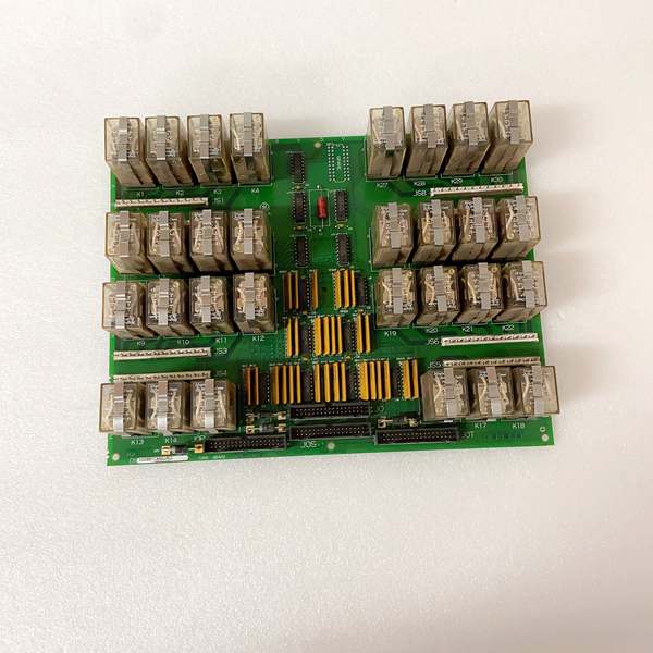
- Status LEDs indicate channel firing status and fault conditions
GE DS200TCRAG1ACC
Field Service Pitfalls: What Rookies Get Wrong
Firing Angle Drift After Crystal AgingThe board ran for ten years, and now the firing angles drift 3-5 degrees between startups. The 11MHz crystal oscillator has drifted—aging quartz changes frequency over time. Tech recalibrates, but drift comes back after thermal cycling.
- Field Rule: If firing angle drift exceeds 1° after warmup, the crystal is at end-of-life. Recalibration is temporary—replace the board or the crystal oscillator module. For critical applications, verify firing angle with an oscilloscope during scheduled outages.
Ignoring Line Synchronization LossThe amber “IMOK” LED flickers when the plant VFDs ramp up. The line sync circuit is seeing noise and losing zero-crossing detection. Firing angles drift from line phase, and the exciter output goes uncontrolled.
- Quick Fix: Verify the line synchronization input is wired directly from the PT secondary—never share the signal with other loads. Add a line filter if EMI is severe. The board needs clean zero-crossing detection—noise causes sync loss and firing chaos.
Misconfiguring Pulse Width for Load TypeSetting 120° pulse width for a highly inductive load. The thyristor stays conduction-locked after the natural commutation point, and you get runaway DC bus voltage. The output rectifier blows, and you’re replacing SCRs.
- Field Rule: Pulse width depends on load power factor. For inductive loads (PF < 0.9), use 10-30° pulses. For resistive loads, 60-90° is fine. Never exceed the commutation margin—calculate: Pulse Width < 180° – Load Angle. If in doubt, start narrow (10°) and widen until the output stabilizes.
Installing Auxiliary Board Without Checking Pin AlignmentDropping in the DS3800DFCF daughter board and forcing it into the nylon pins. Two pins don’t align, so the tech bends them. The daughter board sits crooked, and one of the ammeter connections shorts to ground.
- Field Rule: The auxiliary board mounts on four nylon pins—check alignment before pressing down. If pins don’t line up, don’t force it. Verify the daughter board part number matches the NFCF revision—some revisions have different pin spacing.
Commercial Availability & Pricing Note
Please note: The listed price is for reference only and is not binding. Final pricing and terms are subject to negotiation based on current market conditions and availability.


