
Description
DS3800NFCD1L1E: Product Overview
The board serves as a precision firing circuit module within GE’s Speedtronic Mark IV turbine control architecture. Positioned within the control rack assembly, this unit generates the gate pulses necessary to trigger power semiconductor devices—specifically silicon-controlled rectifiers (SCRs) and thyristors—that manage high-power circuits in turbine applications. In the Mark IV’s triple modular redundant (TMR) system, this board operates within each independent control channel, ensuring synchronized firing of power semiconductors for critical functions such as field excitation, starter systems, and high-voltage auxiliary drives.
As a firing circuit board, the unit manages the precise timing and amplitude of gate pulses required to switch high-power thyristors reliably. It receives firing angle commands from the Mark IV microprocessor-based control algorithms and translates these digital commands into precisely timed analog gate pulses that trigger the SCRs at specific points in the AC waveform. This phase-controlled firing regulates power delivery to field windings, starter motors, and other high-voltage auxiliary equipment, enabling smooth starting sequences and controlled acceleration of large turbine-generator sets.
The board features high-voltage isolation circuitry that protects sensitive low-voltage control electronics from the high potentials present on thyristor anode and cathode circuits. The twelve-channel architecture allows simultaneous control of multiple thyristor phases or independent power circuits, supporting complex firing patterns required for three-phase excitation systems or multi-stage starter control. EPROM-based firmware stores site-specific firing sequences, timing maps, and protection algorithms tailored to specific turbine models and power semiconductor configurations.
This board belongs to the DS3800 series of the Mark IV platform, deployed across heavy-duty gas turbines (Frame 3, 5, 6, 7, 9) and LM aeroderivative units. The platform’s distributed architecture allows firing control to execute autonomously while maintaining deterministic synchronization with the turbine’s speed, voltage, and protection systems, ensuring that thyristor firing remains coordinated with the turbine’s operational state.

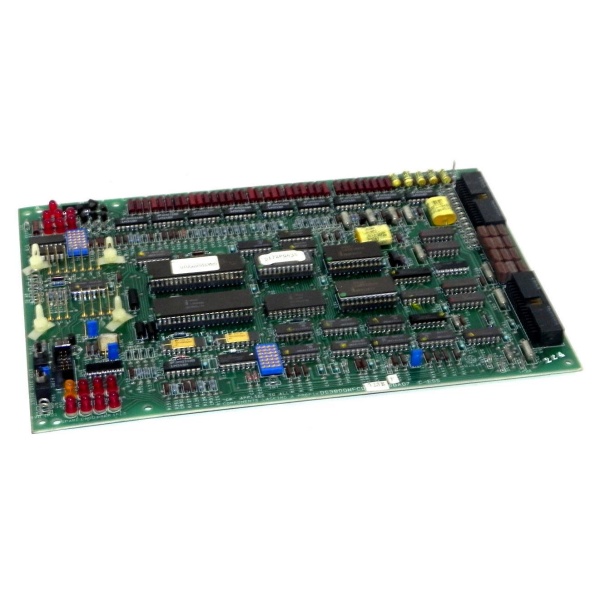
DS3800NFCD1L1E
DS3800NFCD1L1E: Technical Specifications
-
Model Number: DS3800NFCD1L1E
-
Manufacturer: General Electric
-
Product Type: Firing Circuit Board
-
Series: GE Speedtronic Mark IV
-
Architecture: Triple Modular Redundant (TMR) compatible
-
Firing Channels: 12 independent gate pulse outputs
-
Power Semiconductor Interface: SCR/Thyristor gate control (typical 100-500mA gate current capability)
-
Firing Mode: Phase-angle control for voltage regulation
-
Isolation: High-voltage isolation barriers between control logic and gate drive circuits
-
Timing Resolution: Microsecond-level precision for firing angle control
-
Memory: EPROM sockets for firing sequence firmware and timing curves
-
Status Indication: Diagnostic LEDs for firing activity and fault detection
-
Backplane Interface: High-density modular connector (AMD 218A4553-1 compatible)
-
Operating Temperature: -35°C to +45°C (critical thermal management)
-
Storage Temperature: -40°C to +85°C
-
Humidity: 5% to 95% non-condensing
-
Physical Dimensions: 8.24 cm high × 4.16 cm wide (standard Mark IV form factor)
-
Weight: Approximately 2 lbs (0.9 kg)
-
Mounting: Standard Mark IV rack slot with retention levers
-
Power Supply: Derived from Mark IV rack backplane (+5 VDC logic, ±15V analog, high-voltage isolated gate drive supplies)
Part 4: Core Features & Customer Value
Precision Phase-Angle Firing Control: The board generates gate pulses with microsecond-level timing accuracy, enabling precise phase-angle control of thyristor conduction. This precision is critical for generator field excitation systems where firing angle directly regulates field current and generator terminal voltage. By controlling the point in the AC waveform at which thyristors fire, the board enables smooth, stepless voltage regulation from zero to full field current, eliminating the mechanical wear and contact arcing associated with electromechanical voltage regulators.
High-Voltage Isolation and Safety: Integrated optocouplers or pulse transformers provide galvanic isolation between the low-voltage control logic (5V/15V) and high-voltage thyristor circuits (potentially 125-750VDC or 480VAC). This isolation prevents catastrophic failure of control electronics during thyristor faults or line transients, protecting the expensive Mark IV microprocessor boards from high-voltage intrusion. For maintenance personnel, this isolation ensures that control cabinet work can proceed safely without exposure to high potentials present on power semiconductor circuits.
Twelve-Channel Parallel Control Capability: The twelve independent firing channels support complex multi-thyristor applications such as three-phase full-wave rectifier bridges (requiring six thyristors) with redundant triggers, or simultaneous control of multiple auxiliary drives. This channel density reduces board count in high-circuit-count applications, simplifying rack wiring and reducing potential failure points. The parallel channels can be configured for independent operation or synchronized firing patterns depending on turbine application requirements.
Automated Sequence Management: EPROM-stored firmware implements automated firing sequences for turbine startup, field flashing, and shutdown operations. During startup, the board manages the sequential firing of thyristors to build up field current without excessive inrush; during shutdown, it controls controlled de-excitation to prevent generator voltage collapse transients. This automation ensures consistent, repeatable operations regardless of operator skill level and reduces mechanical stress on brushes and slip rings by avoiding sudden field changes.
Comprehensive Diagnostic Protection: The board monitors its own firing outputs for conduction confirmation (via current transformers or voltage feedback) and detects misfires, failed thyristors, or gate circuit opens. These diagnostics prevent continued operation with failed power semiconductors that could cause asymmetric loading or excessive heating. LED indicators provide immediate visual confirmation of firing activity on each channel, enabling rapid identification of failed phases during maintenance without requiring oscilloscope probing of high-voltage circuits.
DS3800NFCD1L1E
Part 5: Typical Applications
Generator Excitation System Control:
The DS3800NFCD1L1E is deployed in GE Frame 5, 6, 7, and 9 gas turbines to control the static excitation system that supplies DC field current to the generator rotor. In these applications, the twelve channels typically control six thyristors arranged in a three-phase full-wave bridge configuration (two thyristors per phase for redundancy). The board receives firing angle commands from the Mark IV automatic voltage regulator (AVR) and generates precisely timed gate pulses to maintain generator terminal voltage within ±0.5% of setpoint. During generator synchronization, the board manages the delicate balance between field current and turbine speed to match grid voltage and frequency.
The DS3800NFCD1L1E is deployed in GE Frame 5, 6, 7, and 9 gas turbines to control the static excitation system that supplies DC field current to the generator rotor. In these applications, the twelve channels typically control six thyristors arranged in a three-phase full-wave bridge configuration (two thyristors per phase for redundancy). The board receives firing angle commands from the Mark IV automatic voltage regulator (AVR) and generates precisely timed gate pulses to maintain generator terminal voltage within ±0.5% of setpoint. During generator synchronization, the board manages the delicate balance between field current and turbine speed to match grid voltage and frequency.
Turbine Starter System Control:
In large gas turbines utilizing static starter systems (reduced-voltage motor starters or wound-rotor motor controls), this board manages the thyristor firing that controls starting torque and acceleration rates. The phase-angle firing gradually increases voltage to the starting motor, preventing mechanical shock to the turbine-compressor train during roll-up. The twelve channels may control multiple stages of starting resistance or multiple parallel thyristors handling high starter currents (hundreds of amperes). The board’s EPROM stores acceleration curves optimized for different turbine inertia and starting conditions, ensuring consistent start times regardless of ambient temperature or grid voltage variations.
In large gas turbines utilizing static starter systems (reduced-voltage motor starters or wound-rotor motor controls), this board manages the thyristor firing that controls starting torque and acceleration rates. The phase-angle firing gradually increases voltage to the starting motor, preventing mechanical shock to the turbine-compressor train during roll-up. The twelve channels may control multiple stages of starting resistance or multiple parallel thyristors handling high starter currents (hundreds of amperes). The board’s EPROM stores acceleration curves optimized for different turbine inertia and starting conditions, ensuring consistent start times regardless of ambient temperature or grid voltage variations.
Static VAR Compensation and Power Factor Control:
In applications requiring reactive power management, the board controls thyristor-switched capacitors or inductors to maintain generator power factor within utility requirements. The twelve channels manage multiple capacitor banks or reactor stages, firing thyristors at voltage zero-crossings to minimize switching transients. This precise switching prevents voltage spikes that could damage turbine auxiliary transformers or disturb plant distribution systems, ensuring clean power quality during reactive power adjustments.
In applications requiring reactive power management, the board controls thyristor-switched capacitors or inductors to maintain generator power factor within utility requirements. The twelve channels manage multiple capacitor banks or reactor stages, firing thyristors at voltage zero-crossings to minimize switching transients. This precise switching prevents voltage spikes that could damage turbine auxiliary transformers or disturb plant distribution systems, ensuring clean power quality during reactive power adjustments.
High-Voltage Auxiliary Drive Control:
For large auxiliary motors such as boiler feed pumps or cooling water pumps utilizing variable voltage thyristor drives, the board controls the six thyristors of a three-phase bridge to provide variable DC voltage to the motor armature. The firing angle control provides smooth speed regulation without the harmonic distortion associated with modern PWM drives, making this approach suitable for sensitive turbine auxiliaries where electrical noise must be minimized. The board’s isolation circuits protect control logic from the high voltage spikes generated by motor commutation.
For large auxiliary motors such as boiler feed pumps or cooling water pumps utilizing variable voltage thyristor drives, the board controls the six thyristors of a three-phase bridge to provide variable DC voltage to the motor armature. The firing angle control provides smooth speed regulation without the harmonic distortion associated with modern PWM drives, making this approach suitable for sensitive turbine auxiliaries where electrical noise must be minimized. The board’s isolation circuits protect control logic from the high voltage spikes generated by motor commutation.
Emergency Field Forcing and Load Rejection:
During grid disturbances or load rejection events, the board manages high-field-forcing conditions where field current must be rapidly increased to maintain generator voltage stability. The twelve-channel redundancy ensures that even if one or two gate circuits fail, the remaining channels can maintain excitation at reduced capacity. The board’s fast response (microsecond-level firing angle updates) supports transient stability requirements, helping generators “ride through” grid faults without losing synchronism.
During grid disturbances or load rejection events, the board manages high-field-forcing conditions where field current must be rapidly increased to maintain generator voltage stability. The twelve-channel redundancy ensures that even if one or two gate circuits fail, the remaining channels can maintain excitation at reduced capacity. The board’s fast response (microsecond-level firing angle updates) supports transient stability requirements, helping generators “ride through” grid faults without losing synchronism.


