
Description
Part 3: Detailed Product Description
DS3800NDID1M1D: Product Overview
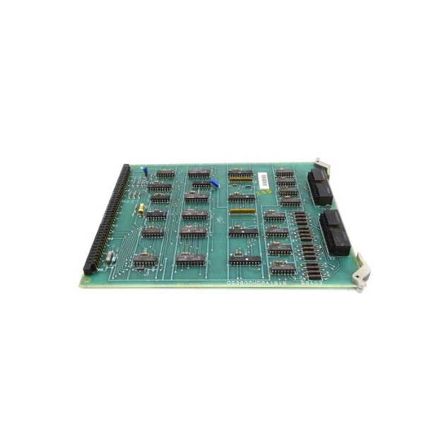
The board serves as a high-complexity interface and expansion module within GE’s Speedtronic Mark IV turbine control architecture. Distinguished by its dual auxiliary daughtercard configuration, this board functions as a versatile host platform for specialized signal conditioning, amplification, and logic translation tasks that extend beyond standard I/O capabilities. In the Mark IV’s triple modular redundant (TMR) system, this board operates within each independent control channel, providing the flexible interface infrastructure necessary for custom or site-specific control adaptations.
As an auxiliary function expander, the board integrates two distinct daughtercards: one labeled 6BA9407P2 (likely a specialized function module) and an unlabeled card populated with multiple amplifiers. These auxiliary cards enable the base board to handle high-channel-count or high-density signal processing tasks without requiring additional rack slots. The board’s architecture supports complex analog and digital signal manipulation, including comparison operations, logic decoding, and linear amplification through its extensive integrated circuit complement.
The board features a multi-connector architecture designed for versatile system integration. Dual 218A4553-1 high-density connectors occupy the left edge for primary backplane communication, while a small ribbon connector and multiple male pin headers provide auxiliary connectivity options. This connectivity diversity allows the board to interface with various subsystems including servo drives, external amplifiers, and specialized sensors that require conditioned power or isolated signal paths.
This board belongs to the DS3800 series of the Mark IV platform, deployed across heavy-duty gas turbines (Frame 3, 5, 6, 7, 9) and LM aeroderivative units. The platform’s distributed processing philosophy enables this board to execute localized signal conditioning and logic operations while maintaining deterministic synchronization with the central control processors through the high-speed backplane.
DS3800HDRA1B1B
DS3800NDID1M1D: Technical Specifications
-
Model Number: DS3800NDID1M1D
-
Manufacturer: General Electric
-
Product Type: Auxiliary Function Expander Interface Board
-
Series: GE Speedtronic Mark IV
-
Auxiliary Cards: 2 removable daughtercards (6BA9407P2 marked card + unlabeled multi-amplifier card)
-
Integrated Circuits: 75+ devices including:
-
Crystal oscillators (timing references)
-
Low power low offset voltage quad comparators
-
Quad 2-input positive OR gates
-
2-line to 4-line decoders/demultiplexers
-
-
Passive Components: Several hundred metal film resistors; mixed capacitor types including BEC 9147 42110 0.50μF ±10% 200V ceramic and electrolytic decoupling capacitors
-
Active Components: 20 transistors for amplification and switching
-
Front Panel Adjustment: 1 rotary potentiometer + 1 trim potentiometer for field calibration
-
Resistor Networks: 2 precision resistor network arrays for voltage division/reference
-
Visual Indicators: 7 LEDs (5 red + 2 amber) + 3 LED strips for status indication
-
Configuration: 6 hardware jumpers (J2 through J6) with options:
-
J2: vf or i (voltage-to-frequency or current mode)
-
J3: r or nr (resistor/no resistor configuration)
-
J4/J5: s or d (single/differential or similar operational modes)
-
J6: off or on (enable/disable or test mode)
-
-
Control Interface: 1 pushbutton switch marked “rst” (reset function)
-
Test Access: 18 test points distributed across circuit nodes
-
Primary Connectors:
-
2× 218A4553-1 A/mp high-density connectors (left edge)
-
1× small ribbon connector (center)
-
2× vertical male pin connectors (middle axis)
-
1× male pin connector 218A4807-P13 (upper right)
-
-
Thermal Management: 1 integrated heatsink for power dissipation
-
Mechanical Support: 2 PCB stiffeners (left edge and 2/3rds position) + 7 nylon spacers
-
Physical Dimensions: Large-format PCB (typical Mark IV dimensions)
-
Operating Temperature: -40°C to +70°C (industrial grade)
-
Humidity: 5% to 95% non-condensing
-
Mounting: Factory-drilled alignment holes with position markings

DS3800HDRA1B1B
Part 4: Core Features & Customer Value
Dual-Auxiliary Architecture for Expanded Capability: The board’s distinctive dual daughtercard design provides hardware extensibility without consuming additional rack slots. The 6BA9407P2 card likely handles specific logic or communication functions, while the unlabeled amplifier card provides multiple channels of signal conditioning. For systems integrators, this architecture allows complex signal processing chains to be implemented within a single board position, reducing rack space requirements and inter-board wiring complexity in crowded control enclosures.
Extensive Logic Processing with Discrete Components: With over seventy-five integrated circuits including comparators, logic gates, and decoders, the board provides substantial local processing capability. The quad comparators enable multiple simultaneous analog threshold detections for alarm monitoring, while the decoder/demultiplexer circuits facilitate address selection and signal routing. This concentration of logic makes the board suitable for applications requiring complex Boolean operations or multi-channel signal selection that would otherwise burden the main microprocessor.
Multi-Format Connectivity Reduces Integration Complexity: The six-connector architecture accommodates diverse interfacing requirements—from high-density backplane connections (218A4553-1) to ribbon cables for internal chassis wiring and male pin headers for field terminations. This versatility allows the board to serve as a protocol or signal format translator, interfacing between the Mark IV’s standardized backplane and specialized external equipment that may use discrete wiring or non-standard communication methods.
Field-Calibration Capability via Dual Potentiometers: The combination of one rotary and one trim potentiometer enables field adjustment of analog parameters such as gain, offset, or threshold levels without software configuration tools. This hardware-level calibration is essential for matching the board to specific sensor characteristics or drive requirements that vary between installations. Technicians can optimize signal levels using standard test equipment, reducing commissioning time and eliminating the need for laptop-based configuration during startup.
Comprehensive Diagnostic Visibility: The seven LEDs (five red, two amber) plus three LED strips provide immediate visual indication of power status, operational states, and fault conditions across multiple circuit zones. This distributed indication scheme allows maintenance personnel to identify functional areas (such as specific auxiliary card operation or comparator outputs) without removing the board or connecting diagnostic equipment. Combined with eighteen test points, this visibility supports rapid fault isolation to the daughtercard or functional block level.
Part 5: Typical Applications
Gas Turbine Servo Drive Interfaces:
The board is deployed in GE Frame 5, 6, and 7 gas turbines to interface between the Mark IV control system and hydraulic servo valves or electromechanical actuators. The dual auxiliary cards handle high-resolution position feedback processing and servo amplifier interfacing. The trim potentiometers calibrate valve null points and gain settings to match specific servo characteristics, while the comparator circuits monitor valve position against command signals to detect sticking or sluggish response. The extensive test points facilitate verification of servo loop stability during commissioning and troubleshooting of vibration-induced wiring issues.
The board is deployed in GE Frame 5, 6, and 7 gas turbines to interface between the Mark IV control system and hydraulic servo valves or electromechanical actuators. The dual auxiliary cards handle high-resolution position feedback processing and servo amplifier interfacing. The trim potentiometers calibrate valve null points and gain settings to match specific servo characteristics, while the comparator circuits monitor valve position against command signals to detect sticking or sluggish response. The extensive test points facilitate verification of servo loop stability during commissioning and troubleshooting of vibration-induced wiring issues.
Steam Turbine Protection System Expansion:
In steam turbine applications within paper mills and petrochemical facilities, this board expands the Mark IV’s capability to monitor additional protective sensors—such as bearing temperature switches, axial position probes, and differential expansion sensors—beyond the capacity of standard I/O boards. The auxiliary amplifier card conditions low-level signals from proximity probes, while the logic gates implement voting logic for redundant sensors. The amber LEDs indicate alarm states for specific protection zones, allowing operators to identify which bearing or measurement point requires attention during upset conditions.
In steam turbine applications within paper mills and petrochemical facilities, this board expands the Mark IV’s capability to monitor additional protective sensors—such as bearing temperature switches, axial position probes, and differential expansion sensors—beyond the capacity of standard I/O boards. The auxiliary amplifier card conditions low-level signals from proximity probes, while the logic gates implement voting logic for redundant sensors. The amber LEDs indicate alarm states for specific protection zones, allowing operators to identify which bearing or measurement point requires attention during upset conditions.
Aeroderivative Turbine Package Customization:
For LM6000 and LM2500 units, the board accommodates package-specific interfaces such as fuel forwarding system controls, inlet guide vane actuators, and compressor bleed valve management. The jumper configurations adapt the board for different operational modes (isochronous speed control, droop load sharing, or temperature control) without hardware changes. The reset pushbutton allows field technicians to manually reset specific control logic or clear fault latches during startup sequences, facilitating commissioning activities in remote locations where diagnostic software access may be limited.
For LM6000 and LM2500 units, the board accommodates package-specific interfaces such as fuel forwarding system controls, inlet guide vane actuators, and compressor bleed valve management. The jumper configurations adapt the board for different operational modes (isochronous speed control, droop load sharing, or temperature control) without hardware changes. The reset pushbutton allows field technicians to manually reset specific control logic or clear fault latches during startup sequences, facilitating commissioning activities in remote locations where diagnostic software access may be limited.
Excitation System Signal Conditioning:
In generator excitation applications, the board processes feedback signals from field current sensors and voltage regulators. The quad comparators monitor field current against over-excitation limits, while the crystal oscillators provide stable timing for firing angle calculations in static exciter controls. The daughtercards may house isolation amplifiers that separate high-voltage field circuits from the low-voltage Mark IV logic, while the main board handles the logic sequencing for field flashing and de-excitation operations during synchronization or fault conditions.
In generator excitation applications, the board processes feedback signals from field current sensors and voltage regulators. The quad comparators monitor field current against over-excitation limits, while the crystal oscillators provide stable timing for firing angle calculations in static exciter controls. The daughtercards may house isolation amplifiers that separate high-voltage field circuits from the low-voltage Mark IV logic, while the main board handles the logic sequencing for field flashing and de-excitation operations during synchronization or fault conditions.
Auxiliary Equipment Control Centers:
The board manages interfaces with auxiliary motor control centers (MCCs), lubrication system panels, and hydraulic power units. It translates Mark IV discrete commands into sequences that coordinate multiple auxiliary devices through the relay logic and decoders. The resistor networks establish proper voltage levels for contactor coils and indicator lamps, while the transistors switch low-power control signals. The board’s ability to host auxiliary function cards allows customization for site-specific auxiliary equipment without modifying the base Mark IV hardware configuration.
The board manages interfaces with auxiliary motor control centers (MCCs), lubrication system panels, and hydraulic power units. It translates Mark IV discrete commands into sequences that coordinate multiple auxiliary devices through the relay logic and decoders. The resistor networks establish proper voltage levels for contactor coils and indicator lamps, while the transistors switch low-power control signals. The board’s ability to host auxiliary function cards allows customization for site-specific auxiliary equipment without modifying the base Mark IV hardware configuration.


