
Description
DS3800NDCA1A1A: Product Overview
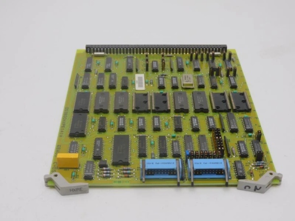
The board serves as a drive characteristic calibration and signal conditioning module within GE’s Speedtronic Mark IV turbine control architecture. Positioned within the control rack, this board functions as a critical interface between the microprocessor-based control system and analog drive systems requiring precise calibration matching. In the Mark IV’s triple modular redundant (TMR) system, this board operates within each independent control channel, ensuring that drive characteristics remain calibrated consistently across redundant control paths.
As a drive characteristic board, the unit provides the analog signal scaling, offset adjustment, and response shaping necessary to match specific drive amplifiers and servo systems to the Mark IV’s control outputs. The extensive array of field-adjustable potentiometers allows qualified technicians to calibrate gain factors, deadband compensation, and linearization curves without software reconfiguration or board replacement. This hardware-level calibration capability is essential when interfacing with legacy drive equipment or when compensating for variations in analog servo characteristics between different manufacturers or equipment ages.
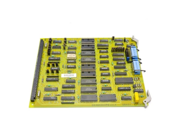
The board features a versatile construction designed for both standalone mounting and sub-assembly integration. The forty-seven component towers with screw terminals provide flexible infrastructure for adding discrete components such as diodes, capacitors, or additional resistors to customize the drive interface for site-specific requirements. The metal shield dividers along the board edges provide electromagnetic interference protection for sensitive analog calibration circuits operating in high-noise turbine environments.
This board belongs to the DS3800 series of the Mark IV platform, deployed across heavy-duty gas turbines (Frame 3, 5, 6, 7, 9) and LM aeroderivative units. The platform’s distributed architecture allows this drive interface to operate autonomously while maintaining deterministic synchronization with the central control processors through the high-speed backplane.

GE DS3800HXPE1A1A
DS3800NDCA1A1A: Technical Specifications
-
Model Number: DS3800NDCA1A1A
-
Manufacturer: General Electric
-
Product Type: Drive Characteristic Board
-
Series: GE Speedtronic Mark IV
-
Calibration Elements: 15 trimmer potentiometers (variable resistors)
-
10 potentiometers grouped in one corner
-
5 potentiometers on opposite edge
-
-
Passive Components: 35 precision resistors with color-coded bands
-
Visual Indicators: 8 LEDs (5 yellow, 3 red) for status indication
-
Component Mounting: 47 short towers with flat-head screws for discrete component attachment
-
Primary Connector: 1 large female terminal for drive interface
-
Mechanical Features:
-
2 thin metal dividers/shields along long edges (EMI protection)
-
2 grey retention clips on one short edge
-
2 screw mounting holes on opposite short edge
-
-
Alignment Markings: Edge labeled A through J (skipping I) for rack alignment
-
Mounting Options: Standalone or stacked/sub-assembly mounting
-
Operating Temperature: -40°C to +70°C (industrial grade)
-
Humidity: 5% to 95% non-condensing
-
Physical Construction: Rigid PCB with component towers and shielding
Part 4: Core Features & Customer Value
Extensive Field Calibration Capability: The fifteen independent trimmer potentiometers provide unprecedented hardware-level adjustment capability for drive signal conditioning. Unlike boards with fixed resistors or software-only calibration, this design allows technicians to match drive characteristics precisely to field equipment during commissioning or maintenance. For drive systems exhibiting wear-related drift or non-linear response, these adjustments compensate for mechanical degradation without requiring expensive drive replacements, extending the operational life of existing auxiliary equipment.
Flexible Component Integration: The forty-seven screw-terminal towers enable field modification of the drive interface circuit to accommodate special requirements. Technicians can add suppression diodes for inductive loads, filter capacitors for noise reduction, or additional resistors for custom voltage dividing networks. This flexibility allows the standard board to be adapted to unique site conditions or legacy equipment interfaces without custom manufacturing, reducing spare parts lead times and enabling rapid response to unforeseen installation challenges.
Visual Status Monitoring: The eight LEDs (five yellow, three red) provide immediate visual indication of power presence, signal activity, and fault states across different circuit zones. During troubleshooting, technicians can verify that drive commands are reaching the board, that calibration circuits are powered, and that fault protection circuits have activated without removing the board or connecting test equipment. This visibility reduces diagnostic time during critical outages and supports preventive maintenance inspections.
Robust Analog Signal Conditioning: The metal dividers along the board edges provide electromagnetic shielding for sensitive analog calibration circuits operating in high-noise environments. This shielding prevents cross-talk between drive channels and protects precision calibration settings from drift caused by electromagnetic interference from high-voltage switchgear or variable frequency drives. For instrumentation engineers, this ensures that carefully calibrated drive signals remain stable during Grid disturbances or electrical storms.
Modular Mounting Adaptability: The dual mounting options—standalone in the Mark IV rack or stacked with other circuit boards—provide installation flexibility for space-constrained control enclosures. The alignment markings (A-J) ensure proper orientation during installation, while the retention clips and screw holes provide secure mechanical stability in high-vibration turbine environments. This adaptability supports both original installations and retrofit applications where cabinet space may be limited.
GE DS3800HXPE1A1A
Part 5: Typical Applications
Gas Turbine Fuel Valve Drive Calibration:
The DS3800NDCA1A1A is deployed in GE Frame 5, 6, and 7 gas turbines to calibrate analog drive signals for electro-hydraulic fuel valve servos. In these applications, the fifteen potentiometers adjust the gain and offset of valve position command signals to match specific servo amplifier characteristics, compensating for variations in hydraulic fluid viscosity, valve spring rates, and actuator response times. The component towers allow installation of custom diodes to suppress inductive kickback from servo solenoids, protecting the calibration circuits from voltage transients during rapid valve movements.
The DS3800NDCA1A1A is deployed in GE Frame 5, 6, and 7 gas turbines to calibrate analog drive signals for electro-hydraulic fuel valve servos. In these applications, the fifteen potentiometers adjust the gain and offset of valve position command signals to match specific servo amplifier characteristics, compensating for variations in hydraulic fluid viscosity, valve spring rates, and actuator response times. The component towers allow installation of custom diodes to suppress inductive kickback from servo solenoids, protecting the calibration circuits from voltage transients during rapid valve movements.
Steam Turbine Governor Drive Interface:
In steam turbine applications within paper mills and power plants, this board interfaces the Mark IV speed control outputs with existing governor drive systems. The calibration potentiometers match the analog signal ranges (typically 4-20mA or ±10VDC) to the specific input requirements of Woodward or other legacy governor amplifiers. The yellow LEDs indicate active control channels during load changes, while the red LEDs signal fault conditions such as loss of feedback or drive saturation. This interface allows modernization of turbine controls while retaining proven mechanical governor hardware, reducing capital costs during retrofits.
In steam turbine applications within paper mills and power plants, this board interfaces the Mark IV speed control outputs with existing governor drive systems. The calibration potentiometers match the analog signal ranges (typically 4-20mA or ±10VDC) to the specific input requirements of Woodward or other legacy governor amplifiers. The yellow LEDs indicate active control channels during load changes, while the red LEDs signal fault conditions such as loss of feedback or drive saturation. This interface allows modernization of turbine controls while retaining proven mechanical governor hardware, reducing capital costs during retrofits.
Aeroderivative Auxiliary Drive Control:
For LM6000 and LM2500 units, the board manages analog interfaces with variable frequency drives controlling package auxiliaries such as fuel forwarding pumps and cooling fans. The independent adjustment of fifteen parameters allows optimization of ramp rates, current limits, and speed feedback scaling to match different motor and drive combinations. The metal shields prevent interference between analog drive circuits and the high-frequency switching noise from VFD power electronics, ensuring stable auxiliary operation during turbine startup and load transitions.
For LM6000 and LM2500 units, the board manages analog interfaces with variable frequency drives controlling package auxiliaries such as fuel forwarding pumps and cooling fans. The independent adjustment of fifteen parameters allows optimization of ramp rates, current limits, and speed feedback scaling to match different motor and drive combinations. The metal shields prevent interference between analog drive circuits and the high-frequency switching noise from VFD power electronics, ensuring stable auxiliary operation during turbine startup and load transitions.
Generator Excitation Drive Conditioning:
In generator applications, the board calibrates field current command signals sent to static excitation systems or brushless exciter controls. The potentiometers adjust the relationship between the Mark IV’s voltage regulator output and the actual field current delivered to the generator rotor, compensating for changes in field winding resistance with temperature. The component towers facilitate addition of surge protection devices to safeguard calibration circuits from field flashover events, ensuring reliable voltage regulation during grid disturbances.
In generator applications, the board calibrates field current command signals sent to static excitation systems or brushless exciter controls. The potentiometers adjust the relationship between the Mark IV’s voltage regulator output and the actual field current delivered to the generator rotor, compensating for changes in field winding resistance with temperature. The component towers facilitate addition of surge protection devices to safeguard calibration circuits from field flashover events, ensuring reliable voltage regulation during grid disturbances.
Hydraulic Power Unit Control:
The board interfaces with hydraulic power unit (HPU) servo amplifiers controlling steam turbine inlet valves or gas turbine inlet guide vanes. The extensive calibration capability allows matching the board’s output to specific servo valve flow characteristics (gpm per milliamp), while the LED indicators provide local confirmation of valve command signals during manual valve testing procedures. The mounting flexibility allows the board to be installed directly adjacent to HPU local control panels in remote turbine skids, reducing analog signal cable lengths and noise susceptibility.
The board interfaces with hydraulic power unit (HPU) servo amplifiers controlling steam turbine inlet valves or gas turbine inlet guide vanes. The extensive calibration capability allows matching the board’s output to specific servo valve flow characteristics (gpm per milliamp), while the LED indicators provide local confirmation of valve command signals during manual valve testing procedures. The mounting flexibility allows the board to be installed directly adjacent to HPU local control panels in remote turbine skids, reducing analog signal cable lengths and noise susceptibility.


