
Description
Hard-Numbers: Technical Specifications
- Output Channels: 8 isolated analog outputs
- Output Types: 4-20mA, 0-10V DC, 0-5V DC (configurable)
- Isolation: 1500V AC channel-to-channel, 2500V AC channel-to-ground
- Output Range: 0-20mA (current mode), 0-10V (voltage mode)
- DAC Resolution: 14-bit successive approximation
- Update Rate: 200 updates per second per channel
- Output Accuracy: ±0.1% of full scale
- Operating Temp: -40°C to +70°C
- Terminal Blocks: 4 blocks × 6 terminals each
- LED Indicators: Power (green), Channel Active (8× yellow), Channel Fault (8× red)
- Power Draw: 800mA @ 125V DC
- Weight: 1.2 kg (2.6 lbs)
- Mounting: Backplane via edge connector
- Compatible Controllers: Mark IV, Mark IV Speedtronic
- Revision: 1U1N (enhanced isolation, improved accuracy)

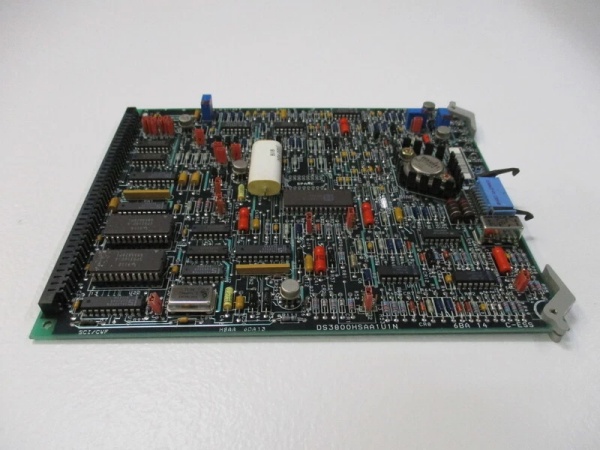
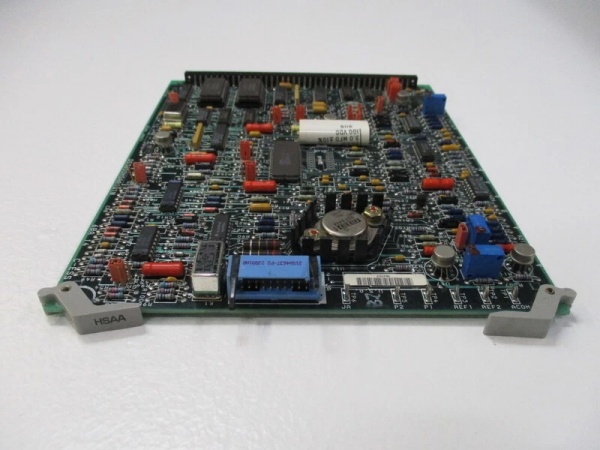
DS3800HSAA1U1N
The Real-World Problem It Solves
Turbine control systems need to drive field devices with precision analog signals—valve positioners expect 4-20mA, hydraulic actuators need 0-10V, and some controllers require 0-5V. When you’re driving multiple devices from a single point source, ground loops and voltage drops cause erratic positioning. This board provides isolated outputs, so each device gets a clean signal unaffected by the others.
Where you’ll typically find it:
- Mark IV turbine control racks driving steam valve positioners
- Gas turbine IGV and fuel valve actuator control outputs
- Hydraulic servo valve command signal generation
- Excitation system control signal interfaces
Bottom line: 8 channels of isolated analog output—each device gets its own clean signal without interference from the rest.
Hardware Architecture & Under-the-Hood Logic
This is an analog output board with isolated DACs per channel. Each output channel has its own DAC, isolation barrier, and output stage. No onboard processor—all scaling and output commands come from the main controller. The 1U1N revision adds enhanced isolation circuits.
- Digital command from main controller enters via backplane bus
- Command routing logic directs data to appropriate channel DAC
- 14-bit DAC converts digital value to analog voltage
- Output scaling circuit conditions signal to specified range
- Isolation amplifier provides galvanic isolation per channel
- Current mode: voltage-to-current converter drives 4-20mA output
- Voltage mode: buffer amplifier drives 0-10V output
- Output protection circuit limits current and clamps overvoltage
- Fault detection monitors output open/short conditions
- Status LEDs indicate active and fault states per channel
DS3800HSAA1U1N
Field Service Pitfalls: What Rookies Get Wrong
Wiring Loads Without Common GroundConnecting eight valve positioners to different field power sources without a common reference. Channel 4’s positioner has its common tied to ground, Channel 5’s common is floating at 50V. The isolation barriers break down, and Channel 5’s output clips at 8V.
- Field Rule: All device commons must be at the same potential reference. If field devices have different power sources, verify the isolation rating is sufficient for the potential difference. If not, use external isolation amplifiers or reorganize the power distribution.
Driving Capacitive Loads Without Current LimitingConnecting a 100µF capacitive load directly to a 0-10V output. The output amplifier tries to drive the capacitor at maximum slew rate, overheating the output stage. Within 20 minutes, the output is permanently damaged.
- Quick Fix: Add a 100Ω series resistor between the board output and capacitive load. Limits inrush current and protects the output amplifier. For large capacitive loads, verify the board’s output current capability—most boards are rated 20mA max on voltage outputs.
Ignoring Open-Loop Fault IndicationSeeing a red fault LED on Channel 3 and bypassing it because “the valve still moves.” The open-loop detection is telling you the 4-20mA loop is broken—either the wire is cut or the positioner’s input resistor failed. The valve is moving, but you have no feedback.
- Field Rule: Fault LEDs mean the output cannot reach the commanded value. If the device is still moving, you’re in an open-loop condition—dangerous for turbine control. Measure the loop current at the device terminal. If you don’t see commanded current, find the break and fix it.
Output Drift After WarmupThe board sits at 50°C ambient. After an hour, Channel 6 output drifts 0.2% from setpoint. Tech recalibrates, but it drifts again after the next thermal cycle. The DAC reference diode is aging and can’t hold stable at temperature.
- Field Rule: If drift exceeds 0.1% after warmup, the reference is degrading. Recalibration is temporary—replace the board. For high-precision applications, consider using the board to drive an external precision reference device instead of direct load control.
Commercial Availability & Pricing Note
Please note: The listed price is for reference only and is not binding. Final pricing and terms are subject to negotiation based on current market conditions and availability.


