
Description
Hard-Numbers: Technical Specifications
- Input Channels: 4 isolated pulse inputs
- Input Types: Magnetic pickup, Hall effect, optical encoder, proximity probe
- Input Voltage: 5-24V AC/DC (depending on probe type)
- Frequency Range: 0.1 Hz to 100 kHz per channel
- Pulse Count: Up to 65,535 pulses per revolution (configurable)
- Isolation: 1500V AC (input to logic)
- Operating Temp: -40°C to +70°C
- Terminal Blocks: 4 blocks × 6 terminals each
- LED Indicators: Power (green), Channel Input (4× yellow), Channel Fault (4× red)
- Power Draw: 550mA @ 125V DC
- Weight: 1.0 kg (2.2 lbs)
- Mounting: Backplane via edge connector
- Compatible Controllers: Mark IV, Mark IV Speedtronic
- Revision: 1A1D (enhanced noise immunity, signal filtering)

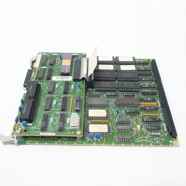
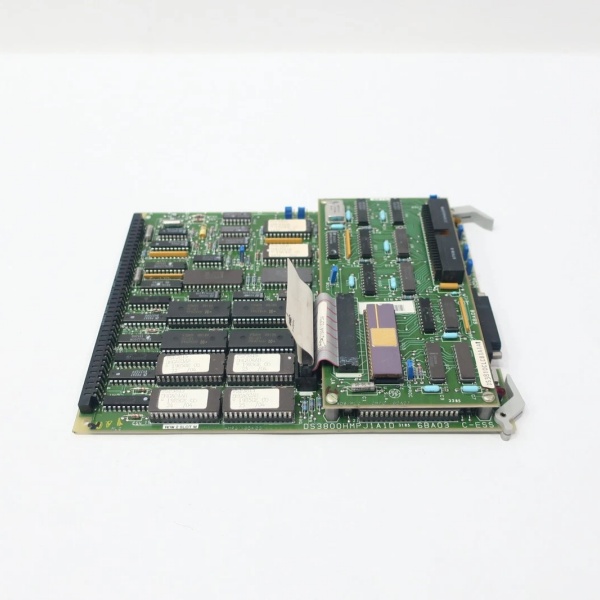
GE DS3800HMPJ1A1D
The Real-World Problem It Solves
Turbine speed signals come in all shapes and sizes—magnetic pickups output millivolt pulses, Hall-effect sensors need pull-up resistors, and optical encoders send square waves. Raw pulses pick up noise from VFDs and motor generators, causing erratic speed readings that trigger overspeed trips. This board conditions different probe types, filters noise, and presents clean frequency data to the governor.
Where you’ll typically find it:
- Mark IV turbine control racks processing main shaft speed signals
- Steam turbine overspeed protection systems
- Gas turbine governor speed feedback loops
- Auxiliary drives and gearbox speed monitoring
Bottom line: Multi-sensor compatibility with noise rejection—keeps speed readings honest even with messy field signals.
Hardware Architecture & Under-the-Hood Logic
This is a dedicated pulse processing board with signal conditioning, frequency-to-voltage conversion, and digital counter logic. Each channel has its own isolation and filtering circuitry. No microprocessor—frequency measurement happens through hardware counters and comparators.
- Pulse signal enters through isolated input terminal block
- Input protection circuit (TVS diodes, clamping diodes) limits voltage
- Signal conditioning circuit amplifies weak magnetic pickup signals
- Schmitt trigger cleans up signal edges and rejects noise
- Hardware counter tracks pulse count per revolution
- Frequency-to-voltage converter generates analog speed reference
- Filter circuits suppress high-frequency noise components
- Fault detection monitors signal loss and invalid pulse patterns
- Isolated output transmits digital frequency data to backplane
- Status LEDs indicate real-time signal presence and health
GE DS3800HMPJ1A1D
Field Service Pitfalls: What Rookies Get Wrong
Mixing Magnetic Pickup and Hall-Effect on the Same BoardWiring a magnetic pickup to channel 1 (configured for Hall-effect) and wondering why the speed reads zero. Magnetic pickups output millivolt-level AC signals—they need the high-gain amplifier path. Hall-effect sensors need 5-24V DC excitation and pull-up resistors.
- Field Rule: Verify probe type before wiring. Magnetic pickups require the AC-coupled input path; Hall-effect and optical sensors need the DC-coupled path with excitation voltage. Configure each channel independently in the controller software.
Running Probe Cables Through the Same Tray as Power FeedersRouting speed probe cables alongside 4160V motor feeders. The EMI induces 60Hz noise on the probe signal, and the board sees erratic speed swings of 50-100 RPM. The governor hunts, and the turbine never settles at stable speed.
- Quick Fix: Route speed probe cables in dedicated steel conduit with individual shielded pairs. Ground the shield at the probe end only—never at both ends. Keep minimum 12-inch separation from power conductors.
Ignoring Signal Loss Fault IndicationSeeing a red fault LED on channel 3 and assuming it’s a board failure. The fault LED means the board 终止ped seeing pulses—either the probe failed, the cable broke, or the air gap is too large. The board is doing its job by reporting signal loss.
- Field Rule: When a fault LED lights, measure the signal at the board terminal with an oscilloscope. If you see clean pulses, the board input stage is bad. If you see nothing or noise, check the probe, cable, and air gap. Magnetic pickups need 0.010-0.030″ air gap—too large, and the signal disappears.
Wrong PPR Configuration for Encoder TypeInstalling a 60-tooth gear with a magnetic pickup but configuring the board for 360 PPR (6× multiplier). The speed reads six times actual, and the governor trips on overspeed at 20% of actual shaft speed.
- Field Rule: Calculate PPR based on your actual sensor configuration. For magnetic pickups, PPR equals the number of gear teeth. For encoders, PPR equals the encoder’s line count. Never assume “360 PPR” is standard—verify with the mechanical drawing or count teeth/lines yourself.
Commercial Availability & Pricing Note
Please note: The listed price is for reference only and is not binding. Final pricing and terms are subject to negotiation based on current market conditions and availability.


