
Description
Key Technical Specifications
-
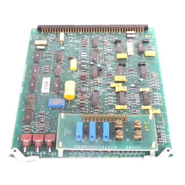
Model Number: DS3800HDPA1A1A
-
Manufacturer: General Electric
-
Logic Voltage: +5 V ±5 % @ 1.2 A from rack back-plane
-
Interface Ports: JA (display data), JB (keypad return), both 0.1″ headers, 20 pos.
-
Signal Levels: 5 V CMOS, 8 mA source/sink, short-circuit protected
-
Cable Length: Rated for 6 ft shielded flat-cable to panel assembly
-
Isolation: 500 Vrms between display field ground and Mark IV logic ground
-
LED Indicators: Green “DRIVE OK,” red “FAULT” latch, visible through bezel
-
EPROM: 2 kB on-board stores character look-up table for 2 × 20 vacuum-fluorescent display
-
Operating Temperature: 0 – 70 °C operational, –40 – 85 °C storage
-
Dimensions: 6.3 × 9.0 in (160 × 229 mm), single-slot 6U Euro-card

GE DS3800NMSM1G1E
Field Application & Problem Solved
In a 1980s peaker the operator doesn’t have a touch-screen—he has a 2 × 20 vacuum-fluorescent display bolted to the cabinet door and a 16-button membrane keypad. The DS3800HDPA1A1A is the card that makes that dumb panel talk to the Mark IV brain. It sits in the right-most rack slot, grabs parallel data off the back-plane, and serializes it down a six-foot ribbon to the display; at the same time it debounces the keypad and shoves the key-code back to the CPU so the operator can start, load, or trip the unit. When the card fails the display goes blank, the keypad is dead, and you’re blind—swap the board and you’re back to 1987 ergonomics in two minutes. You’ll find this PCB in every frame-5/6 that still rocks the original swing-out door display: paper mills, refineries, and municipal utilities that never upgraded to CRT HMIs. Its value is simplicity: no software drivers, no Ethernet—just copper and CMOS that still works after 35 years of coal dust.
In a 1980s peaker the operator doesn’t have a touch-screen—he has a 2 × 20 vacuum-fluorescent display bolted to the cabinet door and a 16-button membrane keypad. The DS3800HDPA1A1A is the card that makes that dumb panel talk to the Mark IV brain. It sits in the right-most rack slot, grabs parallel data off the back-plane, and serializes it down a six-foot ribbon to the display; at the same time it debounces the keypad and shoves the key-code back to the CPU so the operator can start, load, or trip the unit. When the card fails the display goes blank, the keypad is dead, and you’re blind—swap the board and you’re back to 1987 ergonomics in two minutes. You’ll find this PCB in every frame-5/6 that still rocks the original swing-out door display: paper mills, refineries, and municipal utilities that never upgraded to CRT HMIs. Its value is simplicity: no software drivers, no Ethernet—just copper and CMOS that still works after 35 years of coal dust.
Installation & Maintenance Pitfalls (Expert Tips)
Ribbon cable twist—data lines short, display flashes garbage
The flat cable is 1 mm pitch; twist it once and pins 1-2 short. You’ll see random characters or no display at all. Lay the cable in the hinge gutter before you swing the door shut—no sharp bends, no zip-ties on the bend.
The flat cable is 1 mm pitch; twist it once and pins 1-2 short. You’ll see random characters or no display at all. Lay the cable in the hinge gutter before you swing the door shut—no sharp bends, no zip-ties on the bend.
Keypad ground lift—phantom key presses trip the unit
The membrane keypad ground is tied to cabinet sheet-metal. If the door hinge paint breaks down the keypad floats 40 V above logic ground; the CPU reads false “EMERG STOP” and fires the trip solenoid. Run a 14 AWG ground strap from the door frame to the rack star point—problem solved.
The membrane keypad ground is tied to cabinet sheet-metal. If the door hinge paint breaks down the keypad floats 40 V above logic ground; the CPU reads false “EMERG STOP” and fires the trip solenoid. Run a 14 AWG ground strap from the door frame to the rack star point—problem solved.
EPROM window uncovered—character set corrupts
A 2 kB EPROM holds the 5 × 7 character font. Leave the quartz window exposed to fluorescent light and the upper-case alphabet drifts to Klingon. If operators complain about “funny letters,” peel the old foil sticker and slap on fresh HVAC tape—no re-burn needed.
A 2 kB EPROM holds the 5 × 7 character font. Leave the quartz window exposed to fluorescent light and the upper-case alphabet drifts to Klingon. If operators complain about “funny letters,” peel the old foil sticker and slap on fresh HVAC tape—no re-burn needed.
Back-plane pin bend—5 V short on power-up
The 96-pin DIN is soft brass. One bent pin on +5 V arcs as you seat the card and blows the internal trace. Always flashlight-inspect the receptacle; if you see a shiny crescent, straighten it with a jeweler’s screwdriver before insertion.
The 96-pin DIN is soft brass. One bent pin on +5 V arcs as you seat the card and blows the internal trace. Always flashlight-inspect the receptacle; if you see a shiny crescent, straighten it with a jeweler’s screwdriver before insertion.
GE DS3800NMSM1G1E
Technical Deep Dive & Overview
DS3800HDPA1A1A is little more than a parallel-to-serial shift register with CMOS buffers. On the back-plane side it latches a 10-bit word (8 data, strobe, blanking) every 40 ms from the CPU; an on-board 1 MHz ceramic resonator clocks the data out as NRZ serial to the display. Return traffic from the keypad is debounced in hardware (RC + Schmidt trigger) and presented as a 4-bit nibble with valid bit to the CPU on the next scan cycle. A 74138 decoder drives the “DRIVE OK” and “FAULT” LEDs; if the CPU fails to strobe within 200 ms the red LED latches, telling the operator the link is dead. No firmware lives on the card—just combinatorial logic—so you can swap it hot without reloading anything. Treat the ribbon cable like a piece of coax and this board will keep the 1980s display glowing long after the CRT spares are gone.
DS3800HDPA1A1A is little more than a parallel-to-serial shift register with CMOS buffers. On the back-plane side it latches a 10-bit word (8 data, strobe, blanking) every 40 ms from the CPU; an on-board 1 MHz ceramic resonator clocks the data out as NRZ serial to the display. Return traffic from the keypad is debounced in hardware (RC + Schmidt trigger) and presented as a 4-bit nibble with valid bit to the CPU on the next scan cycle. A 74138 decoder drives the “DRIVE OK” and “FAULT” LEDs; if the CPU fails to strobe within 200 ms the red LED latches, telling the operator the link is dead. No firmware lives on the card—just combinatorial logic—so you can swap it hot without reloading anything. Treat the ribbon cable like a piece of coax and this board will keep the 1980s display glowing long after the CRT spares are gone.


