

Description
Hard-Numbers: Technical Specifications
- Input Channels: 2 isolated quadrature encoder inputs (A/B/Z channels)
- Encoder Voltage: 5V DC TTL, 5-24V DC HTL (configurable)
- Resolution: Up to 10,000 pulses per revolution (PPR)
- Maximum Frequency: 500 kHz per channel
- Output Interface: High-speed parallel to DS215 backplane
- Isolation Rating: 1500V AC (input to logic)
- Operating Temp: -40°C to +70°C
- Terminal Blocks: 2 blocks × 12 terminals each
- Signal Termination: 120Ω differential termination (configurable)
- LED Indicators: Power (green), Channel A/B/Z (yellow), Fault (red)
- Coating: BBF conformal coating for harsh environments
- Weight: 0.95 kg (2.09 lbs)
- Mounting: Backplane via standoff pins
- Compatible Controllers: Mark VIe, Mark VI, Mark VIeS

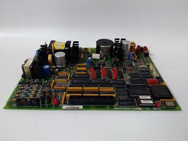
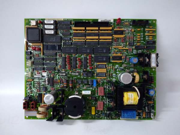
GE DS200TCEAG1B
The Real-World Problem It Solves
Modern turbines use quadrature encoders for precise speed and position feedback—thousands of pulses per revolution that tell the controller exactly where the shaft is at any millisecond. Raw encoder signals are fragile; they get swamped by electrical noise from VFDs, and a single misplaced pulse throws off speed calculation. This board conditions those signals, filters out noise, and presents clean speed data to the controller.
Where you’ll typically find it:
- Steam turbine governor cabinets requiring precise shaft position feedback
- Gas turbine control systems with active clearance control
- Hydro turbine governor racks with multiple encoder inputs
Bottom line: Clean, isolated encoder signal processing prevents false speed readings and unnecessary trips caused by electrical noise in noisy power plant environments.
Hardware Architecture & Under-the-Hood Logic
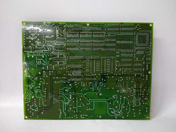
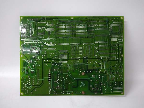
This is a dedicated encoder interface board with signal conditioning, differential receivers, and counter logic. No CPU—just hardware counters and signal processing circuits. The BBF coating seals everything except the terminal blocks.
- Quadrature encoder signals enter through differential input terminals
- Line receivers convert differential A/B/Z signals to single-ended logic
- Schmitt triggers clean up signal edges and reject noise
- Hardware counters track pulse count for position calculation
- Direction detection circuitry determines rotation direction
- Frequency-to-voltage converter generates analog speed reference
- Watchdog circuit detects signal loss or invalid encoder patterns
- Filtered position and speed data transmitted to backplane bus
- Fault detection triggers on signal loss, noise overflow, or wire break
Field Service Pitfalls: What Rookies Get Wrong
Incorrect Termination Resistor SettingsLeaving termination jumpers off on a long cable run. The encoder signals bounce, causing erratic speed readings that oscillate between 0 and 1800 RPM. The governor hunts constantly, and the turbine never settles at stable speed.
- Field Rule: Enable 120Ω differential termination on any cable run over 10 meters. Disable it only for short runs under 2 meters to avoid signal attenuation.
Mixing Encoder Voltage LevelsConnecting a 5V TTL encoder to a board configured for 24V HTL. The weak TTL signals never reach logic threshold, so the board reads zero speed and initiates an emergency trip.
- Quick Fix: Verify encoder supply voltage with a multimeter before wiring. Set JP1-JP4 jumpers to match: 5V position for TTL encoders, 24V position for HTL encoders.
Grounding the Shield Drain Wire at Both EndsCreating a ground loop through the encoder cable shield. The 50Hz noise on the shield couples into the signal lines, causing speed spikes that trigger overspeed trips at no-load conditions.
- Field Rule: Ground encoder cable shields at the encoder end only. Leave the shield drain wire floating at the board terminal block. If cabinet grounding is required, use a shield terminator with a 100V coupling capacitor.
GE DS200TCEAG1B
Commercial Availability & Pricing Note
Please note: The listed price is for reference only and is not binding. Final pricing and terms are subject to negotiation based on current market conditions and availability.


