
Description
Hard-Numbers: Technical Specifications
- Logic Voltage: 5V DC internal / 125V DC field inputs
- Trip Outputs: 4 redundant trip relay channels (2× SPDT, 2× Form C)
- Trip Response Time: <20ms (hardware trip path), <50ms (logic path)
- Input Channels: 24 digital inputs (configurable 125V DC / 24V DC)
- Redundancy: Dual redundant power supplies with diode OR-ing
- Voting Logic: 2-out-of-3 (2oo3) configurable per trip condition
- Isolation Rating: 2500V AC (input to logic, logic to output)
- Operating Temp: -40°C to +70°C
- Terminal Blocks: 4 blocks × 16 terminals each
- LED Indicators: 16 status LEDs (Power, Trip status, Channel health, Fault)
- Coating: 01A conformal coating for marine/offshore environments
- Weight: 2.1 kg (4.63 lbs)
- Mounting: Backplane via rack-mount brackets
- Compatible Controllers: Mark VIe, Mark VI, Mark V retrofit
 The Real-World Problem It Solves
When a turbine overspeeds, you’ve got milliseconds to shut it down before it flies apart. Software-based controllers can hang, lock up, or miss a critical signal. This board puts the trip logic in hardware with a dedicated shutdown path that fires the dump valves even if the main processor crashes. It’s the last line of defense between a safe shutdown and a catastrophic failure.
Where you’ll typically find it:
- Main turbine control racks in fossil-fueled power plants
- Combined-cycle steam turbine emergency shutdown systems
- Critical overspeed protection cabinets in mechanical drive applications
Bottom line: Hardware-based trip logic with redundant voting ensures the turbine shuts down every time, even when the main controller is dead in the water.
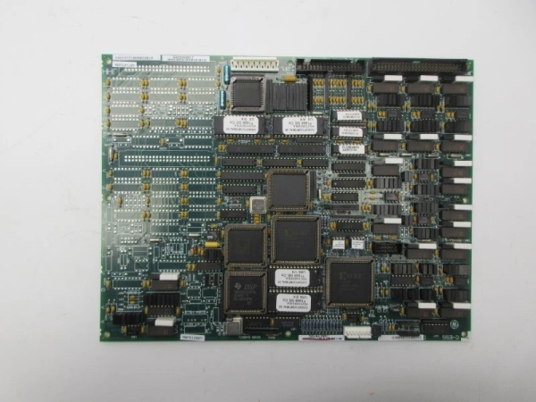
Hardware Architecture & Under-the-Hood Logic
This is a failsafe-critical board with dedicated hardware comparators and voting logic. The trip path is completely independent of the software—signals flow through hardwired comparator circuits that drive relays directly. The 01A coating protects against salt spray in coastal installations.
- Field inputs (overspeed, vibration, bearing temp) enter through isolated terminal blocks
- Signal conditioning circuits convert 125V DC inputs to 5V logic levels
- Trip comparators continuously monitor each input against configured thresholds
- Voting logic (2oo3 or 2oo2) evaluates redundant sensor inputs
- Hardware trip path bypasses CPU—direct relay drive when threshold crossed
- Redundant power rails supply independent trip channels
- Trip latches maintain shutdown state until manual reset
- Watchdog timer monitors CPU health—trips board if processor hangs
- Status LEDs provide real-time trip channel health monitoring
GE DS215TCCBG8BZZ01A
Field Service Pitfalls: What Rookies Get Wrong
Bypassing the Redundant Trip Path for TestingI’ve seen techs disable one trip channel to simulate a fault and “verify the other one works.” Problem is, they forget to re-enable it, and now you’re running on a single-point failure mode. One loose connection and the turbine doesn’t trip when it should.
- Field Rule: Never disable trip channels during normal operation. If you must test, put the controller in maintenance mode with all channels active. Document any bypasses and restore them before restart.
Ignoring Trip Latch Reset SequencePower cycling the board to clear a trip condition. The hardware latches remain set, so the board trips immediately on restart. Then they keep power-cycling, wearing out the relays.
- Field Rule: Trip latches must be reset using the designated reset input or local reset button, not by power cycling. Always verify all trip channels show “healthy” LEDs before releasing the trip reset.
Wiring Overspeed Inputs Without ShieldingRunning overspeed probe cables through the same tray as 4160V motor feeders. The EMI triggers false trips at 2AM, and you’re chasing ghosts while the plant is offline.
- Quick Fix: Route overspeed and vibration inputs in dedicated steel conduit with individual shielded pairs. Ground the shield at the probe end only—never at both ends. Keep a minimum 12-inch separation from power conductors.
Commercial Availability & Pricing Note
Please note: The listed price is for reference only and is not binding. Final pricing and terms are subject to negotiation based on current market conditions and availability.


