
Description
Hard-Numbers: Technical Specifications
- Input Channels: 1 configurable (RTD/TC/4-20mA/0-10V)
- Output Channels: 1 SPDT relay (5A @ 250V AC, 5A @ 30V DC)
- Input Isolation: 1500V AC channel-to-chassis
- Relay Isolation: 2500V AC coil-to-contact
- Operating Temp: -40°C to +70°C
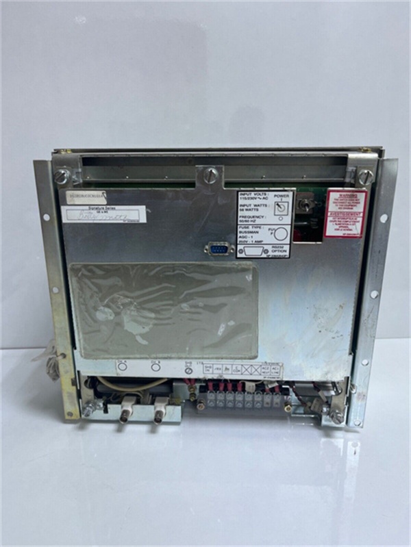
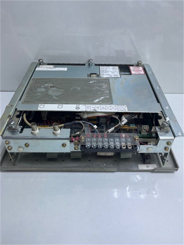
- Terminal Blocks: 3 blocks × 8 terminals each
- Configuration Jumpers: 12 (JP1-JP12 for input type, scaling, alarm thresholds)
- Response Time: <50ms signal-to-relay actuation
- Power Draw: 250mA @ 125V DC
- LED Indicators: Power (green), Signal (yellow), Relay (green), Fault (red)
- Coating: G1A conformal coating for humidity/salt resistance
- Weight: 0.85 kg (1.87 lbs)
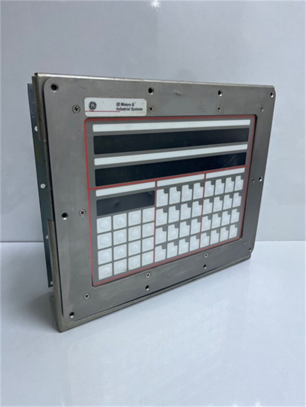
- Mounting: Backplane via standoff pins

GE DS2020UCOCN1G1A
The Real-World Problem It Solves
Turbine controls need to talk to the real world through a rat’s nest of sensor types, and the voltage levels don’t match. This board takes raw field signals—whether it’s a 100Ω platinum RTD or a 4-20mA pressure transmitter—scales them to logic levels, and fires a relay when thresholds trip. Without it, you’d need separate signal conditioners and relay modules for each device.
Where you’ll typically find it:
- Main turbine controller racks interfacing bearing temperature sensors
- Steam valve position feedback loops in combined-cycle plants
- Auxiliary system annunciators requiring isolated relay outputs
Bottom line: One board handles signal conditioning, isolation, and relay output—saves cabinet space and eliminates wiring complexity in harsh environments.
Hardware Architecture & Under-the-Hood Logic
This is an active signal conditioning card with onboard comparator logic and relay driver. No microprocessor; it’s all analog conditioning with discrete threshold detection. The G1A coating seals everything except the terminal blocks and relay socket.
- Field signal enters through isolated input terminal block
- Input scaling circuit (based on jumper settings) converts to 0-10V reference
- Comparator stages compare scaled signal against low/high alarm thresholds
- Relay driver coil energizes when signal crosses threshold
- Optoisolators separate input conditioning from relay output circuit
- Hysteresis circuit prevents relay chatter on borderline signals
- Status LEDs reflect real-time signal level and relay state
- Fault detection circuit triggers red LED on input open/short conditions
GE DS2020UCOCN1G1A
Field Service Pitfalls: What Rookies Get Wrong
Wrong Jumper Configuration for RTD TypeInstalling a 100Ω Pt100 RTD but leaving jumpers set for 1000Ω Pt1000. The board reads 200°C when the actual bearing temp is 20°C, triggering unnecessary trips.
- Field Rule: Always verify sensor type with the vendor documentation before setting JP1-JP4. If the temperature reading is off by factor of 10, your RTD scaling jumpers are wrong.
Forgetting Relay Contact RatingsWiring the board’s relay output directly to a 10A motor starter coil. The contacts weld shut after three trips, and you’re stuck in a run condition when you need an emergency 终止.
- Field Rule: The onboard relay is rated 5A. For loads above 5A, use it to drive an intermediate relay or contactor. Never exceed the contact rating—welded contacts cause dangerous uncontrolled operation.
Ground Loops Through the ShieldGrounding the cable shield at both the field device and this board’s terminal block. The 50Hz hum on the signal line causes erratic relay cycling every time a nearby VFD starts.
- Quick Fix: Ground the shield at the field device end only. Leave the shield drain wire floating at the board terminals. If you need shield continuity to the cabinet, use a shield terminator with a 100V capacitor coupling.
Commercial Availability & Pricing Note
Please note: The listed price is for reference only and is not binding. Final pricing and terms are subject to negotiation based on current market conditions and availability.


