
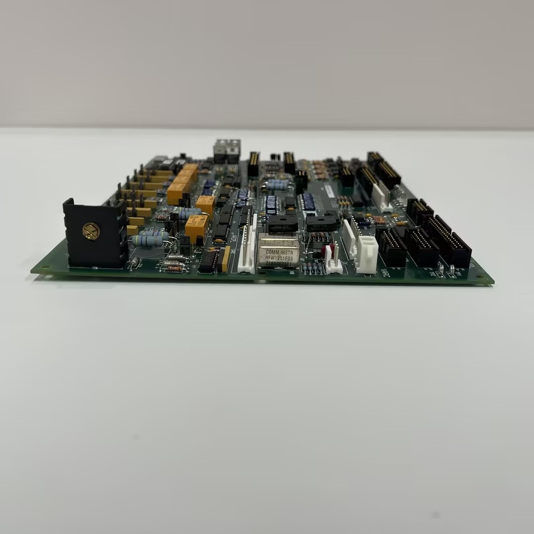
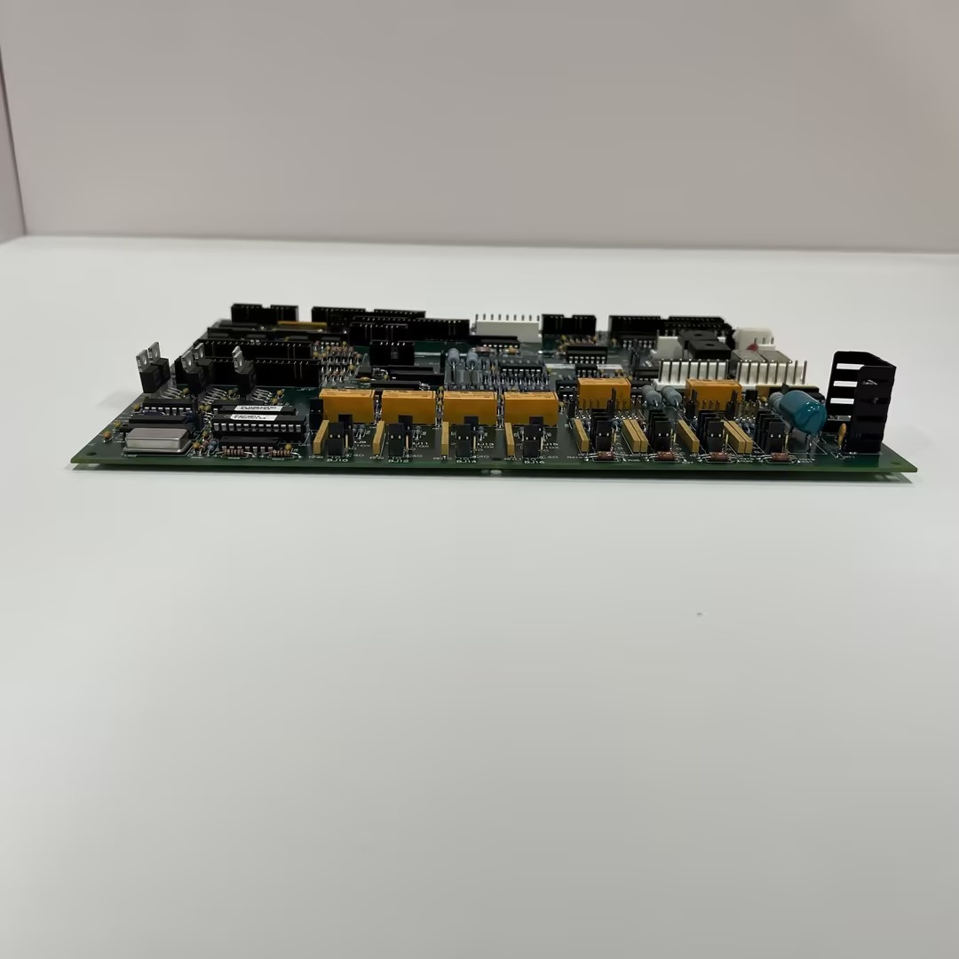
Description
Hard-Numbers: Technical Specifications
- Functional Acronym: FECN (Field Exciter Control Module)
- Current Rating: 15A continuous field current
- Mounting Position: Interior or exterior to drive core
- Configuration Jumpers: 7 (JP1 through JP7)
- Terminal Blocks: 2 (each with 3 terminals)
- Connectors: Multiple prong-type connectors for field and control connections
- Reversing Type: Non-reversing
- Plugging Type: Plugging enabled (NR PLUG = non-plugging design)
- Compatible Frame Sizes: C, G, M
- Used With: DS2000 drives
- PCB Coating: Normal coating (non-conformal)
- Input Voltage: Derived from drive DC bus (typical 125-500V DC)
- Output Voltage: Adjustable field voltage (depends on field winding resistance and current setting)
- Protection Features: Overcurrent, overvoltage, thermal protection
- Manual Reference: GEH-6330B (includes wiring diagrams)
- Wiring Configuration: Flexible wiring options via terminal blocks and connectors
- Weight: Approximately 0.3-0.5 kg (depending on configuration)
- Dimensions: Compact form factor designed for drive cabinet mounting

GE DS200TCQCG1A
The Real-World Problem It Solves
Synchronous motors and generators require precisely controlled DC field current to maintain proper torque characteristics, power factor, and voltage regulation. The DS2020FECNRP015A (15A Field Exciter Board) solves the problem of providing regulated, adjustable DC field current to the field windings, ensuring synchronous machines operate at optimal efficiency and stability. Field current directly affects machine performance—too little current reduces torque and causes motor stall or generator voltage collapse, while excessive current overheats field windings and wastes energy. This board converts drive DC bus power to regulated field current, responding to control commands that adjust field strength based on load conditions, speed requirements, or voltage setpoints. The 15A rating supports medium-sized synchronous machines, providing sufficient current for typical industrial motor and generator field winding requirements. The seven configuration jumpers allow customization for different field winding characteristics—jumpers set current limits, feedback scaling, and control parameters to match specific machine requirements. The “RP” suffix indicates plugging capability, meaning the board can handle field current reversals during regenerative braking or plugging 终止s, while the “X” variant (DS2020FECNRX015A) would be non-plugging for applications that don’t require field reversal. The board’s compatibility with DS2000 drives and frame sizes C, G, M provides flexible integration options across various drive cabinet configurations. Without this dedicated field exciter control, synchronous machines would require separate external excitation systems or manual rheostat adjustments, increasing complexity and reducing control precision. The board’s integrated protection functions prevent field winding damage from overcurrent or overvoltage conditions, extending equipment life and reducing maintenance downtime.
Where you’ll typically find it:
- DS2000 drive cabinets with synchronous motor applications
- Mark V turbine control systems requiring field excitation
- Industrial motor drives with synchronous motors (pumps, compressors, mills)
- Generator excitation systems in power generation facilities
- Retrofits upgrading from lower-current field exciters to 15A capacity
Bottom line: 15A field exciter board with plugging capability—provides regulated DC field current for synchronous machine excitation, with jumper configuration flexibility and integrated protection for reliable operation in DS2000 drive applications.
Hardware Architecture & Under-the-Hood Logic
The DS2020FECNRP015A is a field exciter control board built around power semiconductor switching devices (typically SCRs or IGBTs), current feedback circuits, and control logic that converts drive DC bus power to regulated DC field current. The board receives DC power from the drive DC bus through prong-type connectors, which may range from 125V to 500V DC depending on the drive configuration. This DC input passes through input filtering and protection circuits before reaching the power switching stage—silicon-controlled rectifiers (SCRs) or insulated-gate bipolar transistors (IGBTs) that chop the DC input into pulses. The pulse width and timing of these switches are controlled by the board’s control circuitry, which adjusts duty cycle to regulate the average DC output voltage and current supplied to the field winding. Current sensing circuits monitor the actual field current flowing through the field winding, typically using shunt resistors or Hall-effect sensors that produce a feedback signal proportional to current. This feedback signal passes through scaling and conditioning circuits, with the seven configuration jumpers setting scaling factors, current limits, and feedback parameters to match specific field winding characteristics. The control circuitry compares the scaled feedback against the current reference command from the drive controller, adjusting switching timing to maintain the desired field current. The “RP” plugging capability means the board can control field current in both directions—positive current for normal operation, negative current for regenerative braking or plugging 终止s where the motor field must be reversed to dissipate kinetic energy quickly. This bidirectional control requires a full-bridge switching arrangement that can source and sink current from the field winding. The board outputs to the field winding through the two terminal blocks, each with three terminals providing flexibility for different field winding connections—series, parallel, or tapped field windings can be accommodated by appropriate terminal wiring. Protection circuits continuously monitor for overcurrent (exceeding 15A rating), overvoltage (field voltage too high), and thermal conditions (board overheating). When a fault condition is detected, protection circuits reduce or shut off field current and send fault signals to the drive controller for diagnostic display and corrective action. The seven jumpers (JP1-JP7) configure various operational parameters: current limit settings, feedback polarity, control mode (voltage regulation vs. current regulation), plugging enable/disable, and field winding resistance compensation. These jumpers must be correctly configured for the specific machine requirements—incorrect jumper settings can cause unstable operation, insufficient field current, or overcurrent trips. The board’s compact form factor allows mounting either interior or exterior to the drive core, providing installation flexibility in tight cabinet spaces.
Signal flow:
- DC power received from drive DC bus via prong connectors (125-500V DC)
- Input filtering removes high-frequency noise and transients
- Protection circuits monitor for overvoltage and input faults
- Power switching devices (SCRs/IGBTs) chop DC input into controlled pulses
- Control circuitry generates switching timing based on current reference command
- Field current flows through field winding to output terminals
- Current sensor (shunt or Hall-effect) measures actual field current
- Current feedback signal generated and conditioned
- Scaling circuits adjust feedback based on jumper configuration
- Scaled feedback compared to current reference command
- Error signal drives control circuitry to adjust switching timing
- Pulse width modulation regulates average output voltage/current
- Field current maintained at commanded level via closed-loop control
- Protection circuits monitor for overcurrent, overvoltage, thermal faults
- Fault conditions trigger protection actions and fault signals to controller
- Plugging mode allows bidirectional current flow for regenerative braking
- Terminal blocks provide flexible field winding connection options
- Jumpers configure current limits, scaling, and control parameters
GE DS200TCQCG1A
Field Service Pitfalls: What Rookies Get Wrong
Incorrect jumper configuration for the field windingLeaving jumpers in default positions for a specific machine. I’ve seen technicians installing boards with factory jumper settings that don’t match the field winding characteristics, causing current regulation issues and nuisance trips.
- Field Rule: Always verify jumper configuration matches the machine requirements before installation. Document the original board’s jumper positions and replicate them on the replacement. Default settings are rarely correct—configure jumpers based on field winding resistance, current rating, and application requirements.
Misunderstanding the RP (plugging) capabilityAssuming plugging works automatically without configuration. I’ve seen technicians expecting regenerative braking function without verifying plugging is enabled via jumpers and properly wired, resulting in failed braking attempts.
- Field Rule: Verify plugging is configured correctly if the application requires regenerative braking. Check that jumpers enable plugging mode and that the terminal wiring supports bidirectional current flow. Plugging requires specific jumper settings and wiring—don’t assume it works out of the box.
Overloading beyond 15A ratingConnecting field windings that draw more than 15A. I’ve seen technicians assuming the board handles any field load, then experiencing overcurrent trips and component damage when field current exceeds the rating.
- Field Rule: Verify the field winding’s rated current doesn’t exceed 15A. Calculate expected field current based on winding resistance and voltage requirements. If the machine requires more than 15A, use a higher-rated board (DS2020FECNRP025A, DS2020FECNRP050A, etc.)—don’t exceed the 15A rating.
Incorrect terminal block wiringWiring field windings to the wrong terminal block positions. I’ve seen technicians connecting field leads to the wrong terminals, causing incorrect polarity, insufficient current, or open-circuit conditions.
- Field Rule: Follow the wiring diagram in GEH-6330B for terminal block connections. Verify field winding polarity matches the terminal labeling—incorrect polarity causes improper motor operation or generator voltage issues. Use a multimeter to verify continuity and polarity before energizing.
Ignoring current feedback calibrationAssuming feedback scaling is correct without verification. I’ve seen technicians replacing boards without calibrating the current feedback circuit, resulting in inaccurate current readings and unstable control.
- Field Rule: Calibrate current feedback after replacement. Use a known load or reference current to verify the feedback signal matches the actual field current. Adjust scaling jumpers if necessary—uncalibrated feedback causes regulation errors and potential overcurrent trips.
Not checking field winding resistance before replacementAssuming the old board’s settings work with a new field winding. I’ve seen technicians replacing both the board and the field winding simultaneously but using the old board’s configuration, causing mismatched parameters.
- Field Rule: Measure the new field winding’s resistance before configuring the replacement board. Recalculate current requirements and adjust jumper settings accordingly. Different field windings have different characteristics—don’t assume old settings work.
Neglecting thermal management in high-current applicationsInstalling boards in locations with inadequate cooling. I’ve seen technicians mounting boards in cramped cabinets with poor airflow, causing thermal shutdowns during high-current operation.
- Field Rule: Ensure adequate ventilation and cooling around the board. Maintain clearance for airflow and verify cabinet cooling fans are operational. High-current operation generates significant heat—poor cooling causes thermal trips and premature component failure.
Mixing up RP and RX variantsInstalling the wrong plugging variant for the application. I’ve seen technicians using the non-plugging RX variant when the application requires plugging capability, resulting in failed regenerative braking attempts.
- Field Rule: Verify the correct board variant for the application. RP variants support plugging (field reversal), RX variants are non-plugging. If the application requires regenerative braking or plugging 终止s, use the RP variant—RX boards can’t handle field current reversals.
Forgetting to test protection functionsAssuming protection works without verification. I’ve seen technicians commissioning boards without testing overcurrent and overvoltage protection, only discovering protection circuits are non-functional during actual fault conditions.
- Field Rule: Test protection functions during commissioning. Simulate overcurrent conditions (within safe limits) and verify protection trips correctly. Verify overvoltage and thermal protection are operational. Don’t assume protection works—prove it before returning the system to service.
Improper grounding of the board chassisLeaving the board chassis ungrounded during installation. I’ve seen technicians mounting boards without proper grounding, creating shock hazards and potential noise issues affecting control signals.
- Field Rule: Ensure the board chassis is properly grounded to the cabinet ground. Verify ground connection integrity before applying power. Ungrounded boards pose shock hazards and can cause erratic operation due to ground loops or noise.
Commercial Availability & Pricing Note
Please note: The listed price is for reference only and is not binding. Final pricing and terms are subject to negotiation based on current market conditions and availability. The DS2020FECNRP015A is widely available as new surplus, refurbished, or repaired units, supporting synchronous machine applications requiring up to 15A field current. The board’s 15A rating makes it suitable for medium-sized synchronous motors and generators in DS2000 drive applications, while the plugging capability (RP suffix) enables regenerative braking and rapid 终止ping for applications requiring dynamic braking control. When replacing, verify that the seven jumper configuration matches the original board’s settings or recalculate settings based on field winding characteristics—incorrect jumpers cause unstable operation and potential equipment damage. The board’s compatibility with frame sizes C, G, M provides flexible installation options, but verify the mounting position (interior or exterior to drive core) matches your cabinet configuration. The GEH-6330B manual contains essential wiring diagrams and configuration procedures—consult this manual before installation to ensure correct terminal block wiring and jumper settings. Field winding resistance and current requirements must be calculated or measured before configuring the board—field windings with different resistances require different jumper configurations for proper current regulation. The board’s integrated protection functions prevent field winding damage, but these protections must be tested during commissioning to ensure they operate correctly when needed. For applications requiring higher field current, consider upgrading to the DS2020FECNRP025A (25A), DS2020FECNRP050A (50A), or DS2020FECNRP150A (150A) variants—never exceed the 15A rating, as overcurrent causes component failure and field winding damage. The RP plugging capability is essential for regenerative braking applications—if plugging is not required, the non-plugging RX variant (DS2020FECNRX015A) may provide a cost-effective alternative. Always keep spare jumpers and terminal blocks on hand for field maintenance—correct configuration is critical for reliable operation, and having backup components minimizes downtime during replacements.


