
Description
Hard-Numbers: Technical Specifications
- Functional Acronym: XDSA (Fuel Pressure Management Board)
- Input Channels: 12 analog input channels
- Output Channels: 12 output channels
- Signal Types Supported: LVDT, thermocouple, 4-20mA, 0-10V DC
- Operating Voltage: 12 V DC / 24 V DC input
- Power Supply: 28 V DC
- Power Requirements: +5 V DC at 6 A
- Trip Solenoid Rating: 125 V DC
- Board Dimensions: 100 × 50 × 30 mm
- Weight: 0.3 kg
- Operating Temperature: -40°C to +85°C (-40°F to 185°F)
- Storage Temperature: -40°C to +85°C (-40°F to 185°F)
- PCB Coating: Normal coating (non-conformal)
- Functional Revision 1: A
- Functional Revision 2: C
- Artwork Revision: C
- Communication Protocol: Modbus compatible
- Output Current Range: Configurable via hardware jumper (20mA/200mA)
- Data Conversion: Analog-to-digital conversion with low transmission delay
- Protection Features: Overvoltage, overcurrent, short-circuit protection
- Mounting: Standard PCB mounting with plastic snap holders
- EMI Immunity: Enhanced noise rejection for industrial environments
- LED Indicators: Status and fault indication LEDs for real-time diagnostics
- Instruction Manual: GEH-6153 (Mark V Turbine Control Manual)
- Compatible Turbine Models: LM6000 and other LM series gas turbines

GE DS200TCTGG1AFF
The Real-World Problem It Solves
Gas turbines require precise fuel pressure control to maintain stable combustion and efficient power generation. The DS200XDSAG1ACC (Fuel Pressure Management Board, Revision C) solves the problem of accurate fuel pressure monitoring by processing analog signals from multiple pressure sensors and converting them to digital values for real-time control. The board handles LVDT position signals from fuel control valves, thermocouple temperature readings from fuel lines, and 4-20mA pressure transducer outputs—converting all these signal types into standardized digital data the Mark V controller can use. Precise fuel pressure regulation ensures optimal air-fuel ratio, preventing lean burn conditions that cause combustion instability or rich burn conditions that waste fuel and increase emissions. The board’s 12-channel capacity allows monitoring multiple pressure points throughout the fuel system—supply pressure, manifold pressure, injector pressure—providing comprehensive fuel system visibility. Revision C includes enhanced EMI immunity to prevent signal corruption in electrically noisy turbine environments, improved analog-to-digital conversion accuracy, and configurable output current ranges (20mA/200mA) via hardware jumpers to accommodate different load requirements. The board’s wide operating temperature range (-40°C to +85°C) ensures reliable operation in extreme turbine compartment conditions, while built-in overvoltage, overcurrent, and short-circuit protection safeguards the board and connected sensors. Without this dedicated fuel pressure management, turbines would experience combustion instability, increased emissions, fuel waste, and potential equipment damage from pressure surges or insufficient fuel flow.
Where you’ll typically find it:
- Mark V turbine control cabinets in LM6000 gas turbine installations
- Fuel pressure control panels in LM series gas turbine systems
- Behind drive control cards in Mark V rack assemblies
- Petrochemical plants with gas turbine-driven compressors
- Power generation facilities with aeroderivative gas turbines
Bottom line: 12-channel fuel pressure management board—Revision C provides enhanced EMI immunity and configurable output ranges while ensuring precise fuel pressure monitoring for stable turbine combustion and efficient fuel distribution.
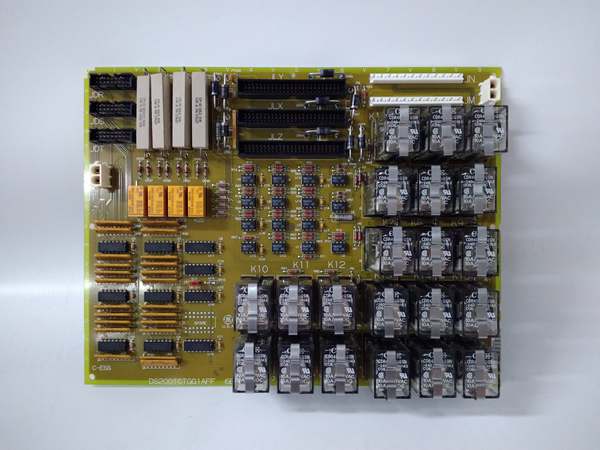
Hardware Architecture & Under-the-Hood Logic
The DS200XDSAG1ACC is an analog signal processing board built around multiple A/D converters and signal conditioning circuits that process diverse sensor inputs for fuel pressure monitoring. The board receives 12 analog input signals through dedicated terminal blocks or connectors, each channel supporting different signal types including LVDT position feedback from fuel control valves, thermocouple temperature measurements from fuel lines, 4-20mA pressure transducer outputs, and 0-10V DC voltage signals. Each input channel passes through dedicated signal conditioning circuitry—LVDT signals go through excitation and demodulation circuits to convert AC position signals to DC voltages, thermocouple inputs pass through cold-junction compensation and amplifier circuits, and 4-20mA current inputs convert to voltage through precision shunt resistors. All conditioned signals route to high-precision A/D converters that digitize the analog values with low transmission delay, ensuring real-time data availability for control loops. The digitized values process through input scaling and linearization algorithms to convert raw counts into engineering units (psi, bar, degrees Celsius, valve position percentage). Revision C includes improved EMI filtering with common-mode noise rejection, reducing signal corruption from the electrically noisy turbine environment—filter circuits on each input channel suppress high-frequency noise and transients before conversion. The board outputs 12 control channels configurable via hardware jumpers for 20mA or 200mA output ranges, allowing connection to various valve actuators and control devices. Output circuits use D/A converters to generate analog control signals from digital commands sent by the Mark V processor, with each output channel providing isolated voltage or current outputs to drive external devices. The board communicates with the main Mark V controller through Modbus-compatible protocols, exchanging real-time pressure data and receiving setpoint commands. LED indicators provide instant status feedback—power indicator, channel fault LEDs, communication status, and general board health. Protection circuits monitor all inputs and outputs for overvoltage, overcurrent, and short-circuit conditions, disconnecting affected channels to prevent board damage and alerting operators via LED indicators and fault codes sent to the control system. The wide input voltage range (12V/24V DC) accommodates different power supply configurations, while the 28V DC power rail ensures stable operation during transient conditions. All components use high-quality surface-mount technology with optimized welding processes to resist aging and vibration, ensuring long-term reliability in the harsh turbine compartment environment.
Signal flow:
- Fuel pressure sensor signals received at 12 input channels
- LVDT signals pass through excitation and demodulation circuits
- Thermocouple signals processed through cold-junction compensation
- 4-20mA current signals converted to voltage via shunt resistors
- 0-10V DC signals directly conditioned through voltage dividers
- All signals pass through Revision C enhanced EMI filtering
- Common-mode noise rejection removes interference
- Conditioned analog signals routed to A/D converters
- A/D conversion produces digital values with low latency
- Digital values scaled and linearized to engineering units
- Processed data transmitted to Mark V controller via Modbus
- Controller sends setpoint commands and control outputs
- D/A converters generate analog control signals
- Output circuits provide 20mA or 200mA based on jumper settings
- Control signals drive fuel valve actuators and control devices
- Protection circuits monitor for overvoltage, overcurrent, shorts
- Fault conditions trigger isolation and fault alerts
- LED indicators display board status and channel health
- Real-time pressure data used for combustion control optimization
GE DS200TCTGG1AFF
Field Service Pitfalls: What Rookies Get Wrong
Misconfiguring output current jumpers for the loadSetting 20mA jumpers on 200mA load devices. I’ve seen technicians leaving jumpers in default 20mA position when connecting to 200mA actuators, causing the valves to fail to open or close properly.
- Field Rule: Always verify the load requirements before configuring output jumpers. Check the actuator’s current rating and set the hardware jumper to match—20mA or 200mA. Default settings are rarely correct for your specific application. Document jumper positions on the original board before removal.
Mixing up LVDT and pressure transducer inputsConnecting sensors to the wrong input channels. I’ve seen technicians wiring LVDT position signals to 4-20mA inputs and pressure transducers to LVDT inputs, causing meaningless readings and control instability.
- Field Rule: Map each sensor type to its correct input channel before wiring. LVDTs require dedicated LVDT inputs with excitation, thermocouples need thermocouple-specific inputs with cold-junction compensation, and 4-20mA transducers require current input channels. Never mix signal types—wrong inputs produce garbage data.
Ignoring cold-junction compensation for thermocouplesConnecting thermocouples without compensating for reference junction temperature. I’ve seen technicians treating thermocouple inputs as raw voltage measurements, resulting in temperature readings that drift with ambient temperature changes.
- Field Rule: Always use thermocouple-specific input channels with built-in cold-junction compensation. Never wire thermocouples to general-purpose voltage inputs—the board expects the compensation circuit to be in the signal path. Verify temperature readings at known conditions before commissioning.
Not verifying EMI filtering during commissioningAssuming the board handles electrical noise automatically. I’ve seen technicians installing Revision C boards in high-EMI environments without verifying signal quality, then experiencing erratic pressure readings that trigger false trips.
- Field Rule: Test input signal quality after installation using an oscilloscope. Verify noise levels are within acceptable range—Revision C has enhanced filtering but won’t fix bad wiring or shielding. Check shield connections and ground references—poor shielding defeats the EMI immunity.
Forgetting to calibrate input scaling after replacementUsing default scaling values on new boards. I’ve seen technicians replacing boards without configuring the input scaling and linearization parameters, resulting in pressure readings that don’t match actual values.
- Field Rule: Reconfigure input scaling and linearization parameters after replacement. Transfer the calibration settings from the old board or perform a fresh calibration against reference standards. Default scaling assumes 4-20mA = 0-100%—your transducer may have different ranges.
Overloading output channels beyond rated currentConnecting multiple devices to one output channel. I’ve seen technicians paralleling two actuators on a single 200mA output, exceeding the current rating and causing output driver failure.
- Field Rule: Never exceed the rated output current per channel. 20mA outputs drive single low-power devices—200mA outputs support higher-power loads but still have limits. Calculate total load current before connecting—overloaded outputs burn out the driver circuits.
Neglecting to test trip solenoid circuits during maintenanceAssuming the 125V DC trip solenoid works because it’s powered. I’ve seen technicians skipping trip circuit tests during annual maintenance, only discovering the solenoid won’t fire during an actual emergency.
- Field Rule: Perform a functional trip solenoid test at least annually. Verify the solenoid actuates when the board sends a trip signal. Test both open and close trip commands—don’t assume protection works unless you prove it.
Improperly grounding LVDT shieldsConnecting LVDT shield drains to multiple ground points. I’ve seen technicians creating ground loops by grounding shields at both the sensor and the board, causing erratic position readings and control hunting.
- Field Rule: Ground LVDT shields at the board only. Float the shield at the sensor end—single-point grounding prevents ground loops. Use twisted-pair cables with overall shields—connect the shield drain to the board’s shield terminal, not to chassis ground at the sensor.
Not checking jumper compatibility before firmware updatesUpdating firmware without verifying hardware jumper configurations. I’ve seen technicians applying new firmware versions that expect different jumper settings, causing boards to boot into fail-safe mode.
- Field Rule: Always check the firmware release notes before updating. New firmware versions may require specific jumper configurations—verify compatibility and adjust jumpers if needed. Don’t assume firmware updates are plug-and-play—read the documentation first.
Leaving the board unpowered for extended periodsStoring spare boards in non-climate-controlled environments. I’ve seen technicians pulling boards from storage after years of sitting in humid conditions, only to find corroded connectors and failed components.
- Field Rule: Store spare boards in climate-controlled environments with low humidity. Power cycle boards at least annually to refresh electrolytic capacitors and prevent contact oxidation. Unpowered storage degrades reliability—exercise the boards regularly.
Commercial Availability & Pricing Note
Please note: The listed price is for reference only and is not binding. Final pricing and terms are subject to negotiation based on current market conditions and availability. As a critical fuel pressure management component in Mark V turbine control systems, the DS200XDSAG1ACC Revision C board is widely available as refurbished, repaired, or new surplus units. This revision offers enhanced EMI immunity and configurable output current ranges compared to earlier XDSA revisions, making it the preferred choice for installations in electrically noisy environments or requiring flexible output configurations. When replacing, verify that the hardware jumper settings for output current range (20mA/200mA) match your load requirements—default settings may not be correct for your application. The board’s 12-channel capacity supports comprehensive fuel system monitoring, but ensure input channel assignments match your sensor configuration—LVDT, thermocouple, and 4-20mA inputs must correspond to the correct signal types. Revision C’s enhanced EMI filtering improves signal quality in high-noise turbine environments, but proper shielding and grounding practices are still essential—bad wiring can overwhelm even improved filtering. Due to the safety-critical nature of fuel pressure control, calibration after installation is mandatory—verify all input scaling and linearization parameters match your transducer ranges and test all output channels against known loads before returning the turbine to service. The board’s wide temperature range allows installation in harsh turbine compartments, but verify that the operating environment remains within -40°C to +85°C specifications—exceeding these limits causes unreliable operation and premature failure. Always keep spare jumpers and calibration documentation on hand for field maintenance—proper jumper configuration and calibration are essential for accurate pressure measurement and reliable fuel control.


