
Description
Hard-Numbers: Technical Specifications
- Functional Acronym: VPBL (Voltage Protection Logic Board)
- Protection Type: Relay-based discrete logic with programmable setpoints
- Input Channels: Multiple analog inputs for voltage monitoring (typically PT inputs)
- Trip Outputs: Hardwired trip relays for protective shutdown
- Status Indicators: Multiple LEDs for fault status and board health
- Trip Functions: Overvoltage, undervoltage, overfrequency, underfrequency protection
- Programmable Setpoints: Adjustable via DIP switches or configuration modules
- Response Time: Fast-acting relay response (typically <50ms)
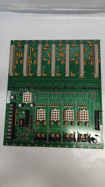
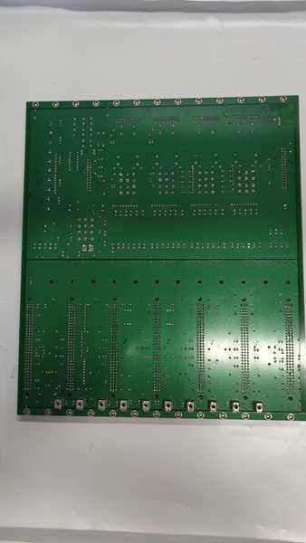
- Board Dimensions: 8.5 × 11 inches (215.9 × 279.4 mm)
- PCB Coating: Normal coating (non-conformal)
- Revision Level: A (current production)
- Mounting: 4 corner mounting holes with plastic snap holders
- Operating Temperature: 0°C to 55°C (32°F to 131°F)
- Power Requirements: 24 V DC from Mark V power supply
- Safety Compliance: ANSI/IEEE C37.90 and IEC 60255 protection relay standards
- Instruction Manual: GEH-6153 (Mark V Turbine Control Manual)
- Connection Type: Pluggable terminal blocks or edge connectors

DS200VPBLG2A
The Real-World Problem It Solves
Turbine and generator equipment needs fast, reliable protection against dangerous operating conditions that could cause catastrophic damage. The DS200VPBLG2A (Protection Board, Revision A) solves the problem by providing independent, relay-based protection logic that monitors voltage parameters and executes protective trips without relying solely on the main processor. This backup protection layer ensures that if the primary control system fails or experiences a fault, critical protective actions still occur fast enough to prevent equipment damage or personnel injury. The board monitors generator voltage levels, frequency deviations, and other electrical parameters, comparing them against programmable setpoints. When a parameter exceeds safe limits, the board directly fires trip relays to disconnect the generator or initiate emergency shutdown. The relay-based design provides inherent reliability—trips execute through electromechanical relays rather than software, ensuring protection even during system lockups or processor failures. Revision A updates include improved trip timing accuracy, enhanced noise immunity on input circuits, and compatibility with updated Mark V system architectures. Without this dedicated protection board, turbines and generators would rely solely on software-based protection, creating a single point of failure that could allow destructive conditions to persist during control system anomalies.
Where you’ll typically find it:
- Mark V turbine control cabinets in gas, steam, and combined-cycle power plants
- Generator protection panels in utility-scale power generation facilities
- Voltage protection relaying sections in speedtronic control systems
- Behind drive control cards in Mark V rack assemblies, providing independent protection layer
- Retrofits upgrading from earlier VPBL revisions to Revision A for improved performance
Bottom line: Independent relay-based voltage protection board—Revision A provides fast-acting backup protection with improved noise immunity and timing accuracy, ensuring critical equipment safety even during primary control system failures.
Hardware Architecture & Under-the-Hood Logic
The DS200VPBLG2A is a protection logic board built around discrete relay circuits and analog comparators that execute protective trip functions independent of the main Mark V processor. The board receives analog voltage signals from potential transformers (PTs) representing generator terminal voltage and frequency, conditions these signals through isolation transformers and filtering circuits to remove noise and transients, then passes them to comparator circuits that compare the measured values against programmable setpoints established via DIP switches or configuration resistors. When a monitored parameter exceeds its setpoint threshold, the comparator circuit triggers a latching relay that closes a trip contact, initiating protective shutdown actions. The trip outputs are hardwired to breaker trip coils, emergency 终止 circuits, or other protective devices—these are electromechanical relays, not solid-state switches, providing fail-safe operation that doesn’t depend on software or control power status. Revision A includes improved input filtering with common-mode noise rejection, reducing nuisance trips from electrical interference often seen in high-EMI environments. The board also includes LED indicators for each protection function, showing which parameter initiated the trip and providing immediate diagnostic information during fault investigation. The protection logic is purely hardware-based—no microprocessor or firmware involved—ensuring deterministic response time and eliminating the risk of software bugs or lockups preventing protective action. The board operates on 24 V DC power from the Mark V system but includes capacitive hold-up allowing trip relay firing even during brief power interruptions. This protection layer operates in parallel with the main processor-based protection, providing redundancy—if either system detects a fault, the trip executes, ensuring no single point of failure disables equipment protection.
Signal flow:
- Generator terminal voltage measured by potential transformers (PTs)
- Analog voltage signals conditioned through isolation transformers
- Filter circuits remove high-frequency noise and transients
- Voltage dividers scale signals to comparator input range
- Comparator circuits compare measured values to setpoint thresholds
- Revision A improved filtering reduces common-mode noise interference
- Setpoints established via DIP switches or configuration resistors
- Parameter exceeding threshold triggers comparator output
- Latching relay activated by comparator signal
- Trip relay contacts close, completing protective circuit
- Trip signal sent to breaker trip coil or emergency 终止 circuit
- Protective action executed independently of main processor
- Capacitive hold-up allows trip firing during brief power loss
- LED indicators activated for fault diagnostics
- Trip latches until manual reset via reset button or power cycle
- Hardwired protection provides deterministic response time
DS200VPBLG2A
Field Service Pitfalls: What Rookies Get Wrong
Assuming protection board functions are redundant with main processor protectionDisabling or bypassing VPBL trips believing the Mark V processor provides adequate protection. I’ve seen technicians jumpering out VPBL trip contacts during troubleshooting, then forgetting to remove the jumpers, leaving the turbine with no independent protection layer.
- Field Rule: Never disable VPBL protection unless you’re performing a supervised test with all safety precautions. Always remove test jumpers immediately after testing. The VPBL is not redundant—it’s an independent backup protection layer.
Not verifying trip setpoints after Revision A installationInstalling replacement boards with default DIP switch positions. I’ve seen technicians dropping in Revision A boards without copying the switch settings from the original board, then wondering why the turbine trips on normal voltage transients or fails to trip during genuine overvoltage conditions.
- Field Rule: Document every DIP switch and jumper configuration on the original board before removal. Configure the replacement board identically before installation. Verify trip setpoints match the generator’s protection coordination study—default settings are never correct for your specific application.
Mishandling relay coils during testingApplying incorrect voltage to trip relay coils during functional tests. I’ve seen technicians using 125 V DC to test 24 V DC coils, burning out the relay and rendering the protection inoperable.
- Field Rule: Always check relay coil ratings before testing. Most VPBL trip relays are 24 V DC—verify with a multimeter and use the correct test voltage. Testing with wrong voltage destroys the relay and compromises equipment protection.
Ignoring LED fault codes after a tripResetting the board without noting which LED was lit. I’ve seen technicians resetting the VPBL immediately after a trip and returning the unit to service without identifying the root cause, then experiencing repeat trips because the actual condition wasn’t addressed.
- Field Rule: Never reset the VPBL until you’ve documented which LED(s) were illuminated and the trip condition. Check generator voltage, frequency, and other parameters to confirm the trip was valid before resetting. Resetting without investigation hides the real problem.
Neglecting to test trip functions during scheduled maintenanceAssuming protection works because it’s powered up. I’ve seen technicians skipping functional trip tests during annual maintenance, only discovering the VPBL relays have welded contacts or failed coils when an actual fault occurs and protection fails to operate.
- Field Rule: Perform a functional trip test at least annually. Simulate overvoltage or undervoltage conditions and verify the trip relay fires. Test both trip circuits and verify breaker response. Don’t assume protection works—prove it.
Using wrong replacement relays during repairSubstituting generic relays for the specified trip relays. I’ve seen technicians replacing failed trip relays with off-the-shelf components that have incorrect coil voltages or contact ratings, causing trip failures or unreliable operation.
- Field Rule: Only use relays with the exact GE part number specified in the manual. Trip relays must match coil voltage, contact rating, and timing characteristics. Substitutions compromise protection reliability—use genuine replacement parts.
Forgetting to verify isolation before PT wiringWorking on PT input circuits without confirming isolation. I’ve seen technicians getting shocked by PT secondary voltages because they assumed the PT circuits were de-energized when they weren’t.
- Field Rule: Always verify PT secondary circuits are de-energized before working on VPBL input wiring. PT secondaries can be energized from the grid even with the generator offline—measure with a multimeter and confirm zero voltage before touching any terminals.
Not cleaning relay contacts during maintenanceLeaving corroded or oxidized relay contacts in service. I’ve seen technicians ignoring relay contact condition during maintenance, then experiencing trip failures because the contacts can’t carry the required current.
- Field Rule: Inspect relay contacts annually. Clean lightly oxidized contacts with contact cleaner. Replace any relays with pitted, welded, or severely corroded contacts. Dirty contacts cause trip failures—clean or replace them.
Mixing up Revision A and earlier revision setpoint configurationsAssuming all VPBL boards use the same DIP switch patterns. I’ve seen technicians applying Revision A configuration guides to Revision G boards, causing incorrect trip setpoints and nuisance trips.
- Field Rule: Always check the board revision and use the corresponding configuration guide. Revision A has different switch patterns than earlier revisions—verify board revision before programming setpoints. Don’t assume configurations transfer across revisions.
Leaving the board unpowered for extended periodsStoring spare boards without periodic power cycling. I’ve seen technicians pulling VPBL boards from storage after years of sitting on the shelf, only to find the relays are stuck from lack of actuation.
- Field Rule: Power cycle spare boards at least annually. Store in climate-controlled environments. Actuate relays manually or apply test voltage to prevent contact stiction. Unpowered boards can develop relay issues—exercise them regularly.
Commercial Availability & Pricing Note
Please note: The listed price is for reference only and is not binding. Final pricing and terms are subject to negotiation based on current market conditions and availability. As a safety-critical protection component in Mark V turbine control systems, the DS200VPBLG2A Revision A board is widely available as refurbished, repaired, or new surplus units. This revision offers improved noise immunity and trip timing accuracy compared to earlier VPBL revisions, making it the preferred choice for new installations and retrofits requiring enhanced protection performance. When replacing, verify that the DIP switch settings and trip setpoint configurations match the original board’s settings unless you’re updating the protection coordination settings. The board’s relay-based design provides inherent reliability—no firmware updates are required, and protection functions execute deterministically regardless of software status. Due to the safety-critical nature of protection functions, functional testing after installation is mandatory to verify all trip functions operate correctly and setpoints are accurate. Never bypass or disable VPBL protection during normal operation—the independent protection layer is essential for equipment safety. Revision A boards are compatible with most Mark V system architectures but verify compatibility with your specific control cabinet configuration before installation. Always keep spare relays and contact cleaning supplies on hand for field maintenance—relay failures are the most common VPBL board issue and can be quickly repaired with proper parts.


