
Description
Key Technical Specifications
-
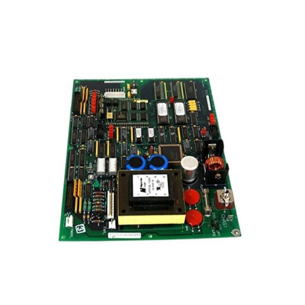
Model Number: DS200UPLAG1B
-
Manufacturer: General Electric (GE)
-
Board Size: 8.5 × 11 in (standard Mark V card footprint)
-
Connectors: 2 × 26-pin, 1 × 8-pin, 1 toggle switch, 1 push-button reset
-
Configuration: 17 jumpers + 16 DIP switches (two blocks of 8) for voltage selection, enable logic, and rail sequencing
-
Output Rails: +5 V (logic), ±12 V (analog), +24 V (relay / fan) – exact current ratings per DIP-switch setting
-
Isolation: Basic insulation, 2 kV input-to-frame; LAN section floated for noise immunity
-
Cooling: Convection; no on-board fan
-
Operating Temperature: –40 °C…+70 °C (ambient inside card-file)
-
Weight: 3.2 lb (1.45 kg)
-
Protection: Input fuse, over-temperature shutdown, reset button for soft-restart without dropping the drive
-
Mounting: Mark V card-file, four-corner screws; matching holes in rack
-
Certifications: CE, UL508 (board level)

GE DS200UPLAG1B
Field Application & Problem Solved
Inside a Mark V or AC2000 cabinet the biggest nuisance is losing the LAN section—gate drivers, comm transceivers, and CPU all drop off-line when the 5 V or 24 V supply browns out. The DS200UPLAG1A/B sits in the same rack and feeds all of those rails from one card; if it trips you lose the whole control side in seconds. You’ll typically find it bolted behind the left-hand door on Frame-7/9 peakers—one board replaces four bricks, reports fuse and temperature status over the internal 28 V logic bus, and still gives you a front-panel reset button so you can reboot the LAN without shutting down the turbine. Core value: it collapses a multi-rail PSU, sequencing logic, and fault annunciation into one plug-in card you can swap in five minutes while the unit is on turning gear.
Inside a Mark V or AC2000 cabinet the biggest nuisance is losing the LAN section—gate drivers, comm transceivers, and CPU all drop off-line when the 5 V or 24 V supply browns out. The DS200UPLAG1A/B sits in the same rack and feeds all of those rails from one card; if it trips you lose the whole control side in seconds. You’ll typically find it bolted behind the left-hand door on Frame-7/9 peakers—one board replaces four bricks, reports fuse and temperature status over the internal 28 V logic bus, and still gives you a front-panel reset button so you can reboot the LAN without shutting down the turbine. Core value: it collapses a multi-rail PSU, sequencing logic, and fault annunciation into one plug-in card you can swap in five minutes while the unit is on turning gear.
Installation & Maintenance Pitfalls (Expert Tips)
Reset Button Is Live at 28 V – Use One Finger Only
The push-button sits on the front edge; if you poke it with a meter probe you’ll short the 28 V logic rail and trip the whole CPU. Press with a plastic tool or one gloved finger—no metal tips.
The push-button sits on the front edge; if you poke it with a meter probe you’ll short the 28 V logic rail and trip the whole CPU. Press with a plastic tool or one gloved finger—no metal tips.
DIP Switches Set Rail Sequencing – Photo Before You Swap
There are 16 switches—one wrong position and the 24 V comes up before 5 V, the LAN chips latch up, and you’ll chase a “comm-loss” that isn’t there. Cell-phone a picture of the old card before you pull it.
There are 16 switches—one wrong position and the 24 V comes up before 5 V, the LAN chips latch up, and you’ll chase a “comm-loss” that isn’t there. Cell-phone a picture of the old card before you pull it.
Input Fuse Is Potted – Don’t Blow It
The mains fuse is under conformal coat; short the output and the board is scrap. Always megger the load cables before first power-up; a grounded fan lead will blow the fuse and you’ll chase a “supply fail” that can’t be field-repaired
The mains fuse is under conformal coat; short the output and the board is scrap. Always megger the load cables before first power-up; a grounded fan lead will blow the fuse and you’ll chase a “supply fail” that can’t be field-repaired
.
Jumpers Control Over-Current Fold-Back – Match the Drawing
JP1-17 select current limits; if you set 5 A on a 10 A fan bank the supply folds back, the fans stall, and the card-file hits 70 °C in ten minutes. Use the settings from GEI-100178 or you’ll discover the weakness during the next heat-wave.
JP1-17 select current limits; if you set 5 A on a 10 A fan bank the supply folds back, the fans stall, and the card-file hits 70 °C in ten minutes. Use the settings from GEI-100178 or you’ll discover the weakness during the next heat-wave.
Technical Deep Dive & Overview
Internally the board is a forward-converter SMPS running at ~100 kHz. The primary side rectifies 120-240 VAC (or 125 VDC battery), feeds a MOSFET switch, and delivers +5 V, ±12 V, and +24 V through separate secondary windings. DIP switches enable/disable each rail and set fold-back current; opto-couplers report “power OK” and fuse status to the DSP. No fan—heat-sink fins are bonded to the card frame; block airflow and the OTP shuts the converter until temperature drops below 70 °C. Swap takes five minutes: pull the card, set the switches/jumpers to match the old unit, land the input lugs, plug the 26-pin cables, and all rails come up in sequence—no external sequencing hardware required
Internally the board is a forward-converter SMPS running at ~100 kHz. The primary side rectifies 120-240 VAC (or 125 VDC battery), feeds a MOSFET switch, and delivers +5 V, ±12 V, and +24 V through separate secondary windings. DIP switches enable/disable each rail and set fold-back current; opto-couplers report “power OK” and fuse status to the DSP. No fan—heat-sink fins are bonded to the card frame; block airflow and the OTP shuts the converter until temperature drops below 70 °C. Swap takes five minutes: pull the card, set the switches/jumpers to match the old unit, land the input lugs, plug the 26-pin cables, and all rails come up in sequence—no external sequencing hardware required
.


