
Description
Hard-Numbers: Technical Specifications
- Functional Acronym: UCPB (I/O Engine CPU Board)
- Functional Revision: 6
- Artwork Revision: A
- PCB Coating: Normal coating (standard Mark V assembly)
- Product Type: I/O Engine CPU Board / Daughterboard
- Processor Type: Intel 80486DX microprocessor (CPU)
- Memory Configuration: DRAM via Single Inline Memory Module (SIMM) socket
- Firmware Storage: Flash Erasable Programmable Read-Only Memory (EPROM) with ROM BIOS and I/O mapped flash EPROM
- Serial Communications: 2 × RS-232 serial ports (COM1, COM2)
- Network Driver: ARCNET driver for COREBUS communication
- DIP Switches: 7-position switch block for COREBUS address configuration
- Jumpers: 3 hardware jumpers (JP1, JP2 for 486 local bus speed selection, JP3 for factory tests)
- Connectors: ARCNET (COREBUS), COM1 (TIMN interface), COM2 (typically unused), J1/J3 (bus connections), IDE (typically unused), 34-pin connector for ribbon cable
- Installation Location: Daughterboard mounted on STCA board in I/O Engines R1, R2, R3, and R5
- PCM Daughterboard Support: R2 IO Engine supports PCM daughterboard for FMVED motor controller serial connection
- Packet Transmission Rate: Fast packets at 100 Hz (10 ms intervals), slow packets at reduced rates
- Data Broadcasting: COREBUS to R core via STCA board
- Configuration Source: IOCFG.AP1 file in Control Engine flash
- Configuration Transfer: 3PL to analog IO boards, IONET to digital IO boards
- Safety Standard: IEC 60947-5-1 compliance
- Instruction Manual: GEH-6153 (Mark V Turbine Control Manual)
- Country of Origin: United States (USA)
- ESD Sensitivity: High—requires ESD protection during handling

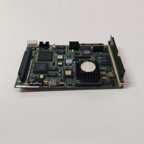
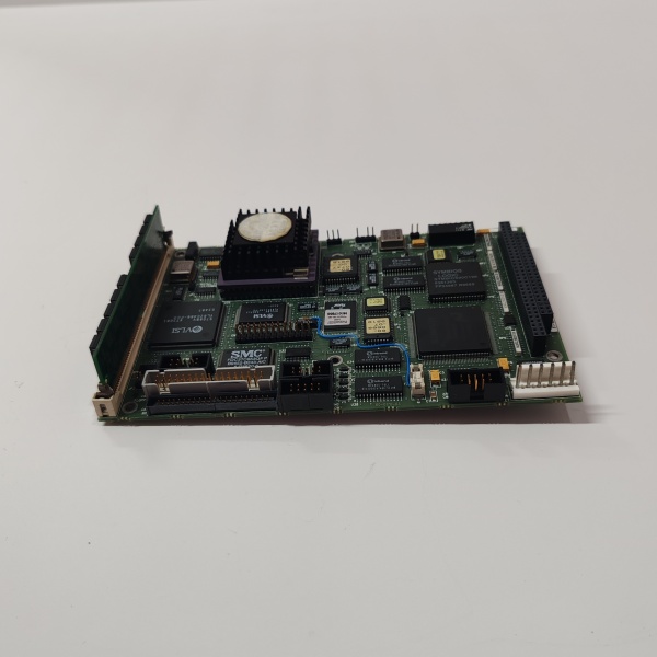
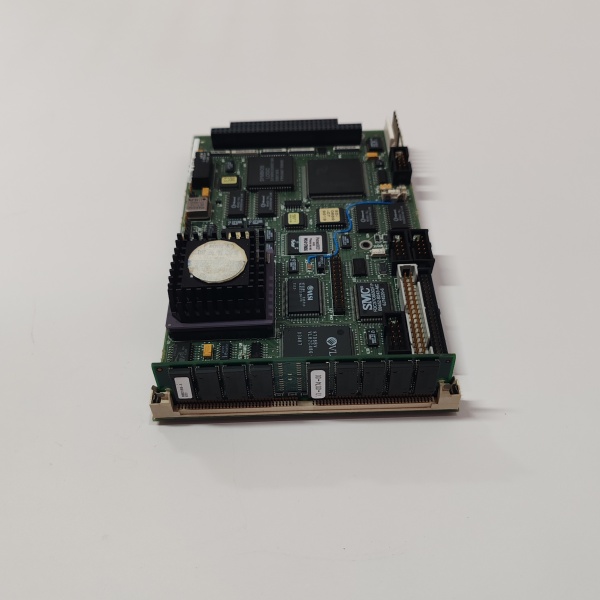
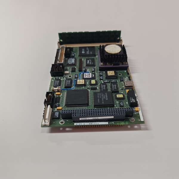
DS200UCPBG6AFB
The Real-World Problem It Solves
The Mark V turbine control system requires dedicated I/O processing capability to manage large volumes of sensor data while maintaining real-time communication with control processors. The DS200UCPBG6AFB (I/O Engine CPU Board) addresses this need by providing a dedicated 80486DX processor in each I/O core (R1, R2, R3, R5) that packages analog and digital I/O data and broadcasts it over COREBUS to the control engine (R core). This board solves the challenge of offloading I/O processing from the main control processors, ensuring that critical control algorithms are not bogged down by data management tasks. The UCPB board operates as a daughterboard mounted on the STCA board in each I/O Engine, receiving I/O data from various I/O boards and organizing it into packets for transmission. Critical data is broadcast in “fast packets” at 100 Hz (every 10 ms) for real-time control requirements, while less critical information is transmitted in “slow packets” at reduced rates to optimize bandwidth utilization. The ARCNET driver provides reliable communication over COREBUS, connecting I/O cores to the R core. The board’s DRAM memory stores I/O configuration data loaded from the Control Engine’s IOCFG.AP1 file during core reboot, which is then distributed to analog and digital IO boards via 3PL and IONET connections. In R2 IO Engine, the UCPB supports a PCM daughterboard for serial communication with FMVED motor controllers, extending its functionality to motor control applications. Without this dedicated I/O processing capability, the Mark V system would need more powerful control processors or would experience performance bottlenecks in data handling, compromising real-time control capabilities.
Where you’ll typically find it:
- I/O Engines R1, R2, R3, and R5 in Mark V control cabinets
- Mounted as daughterboard on STCA board
- Triple-redundant I/O core architecture
- Gas turbine control systems
- Steam turbine control systems
- Mark V Speedtronic control racks
Bottom line: Dedicated I/O Engine CPU processor—providing 80486DX-based I/O data packaging, COREBUS broadcasting, and configuration management for Mark V turbine control system I/O cores.
Hardware Architecture & Under-the-Hood Logic
The DS200UCPBG6AFB (Revision 6A) is the I/O Engine CPU Board designed as a daughterboard mounted on the STCA (Signal and Terminal Control Assembly) board in each I/O Engine of the Mark V control system. The board is based on an Intel 80486DX microprocessor that executes I/O data processing tasks independently of the main control processors (R core). The UCPB board receives I/O data from various analog and digital I/O boards connected to the I/O Engine through the STCA board and packages this data into structured packets for transmission over COREBUS. The board’s memory subsystem includes DRAM installed via a SIMM socket, which stores I/O configuration data downloaded from the Control Engine’s flash memory (IOCFG.AP1 file) during core reboot. Firmware is stored in flash EPROM modules containing the ROM BIOS and I/O mapped flash EPROM that control board operation and communication protocols. Communication with the control system occurs through multiple interfaces: the ARCNET driver manages COREBUS communication to transmit and receive data packets to/from the R core; COM1 provides an RS-232 serial interface for the Terminal Interface Monitor (TIMN) via the STCA board; COM2 is a secondary RS-232 port that is typically unused. The board features a 7-position DIP switch block that configures the COREBUS address for each I/O Engine, ensuring unique addressing on the communication bus. Three hardware jumpers provide configuration options: JP1 and JP3 are used for factory testing; JP2 selects the 486 local bus speed for performance tuning. A 34-pin connector provides ribbon cable attachment to the drive interior for board-to-board communication. The UCPB board implements a dual-rate packet transmission scheme: “fast packets” are transmitted at 100 Hz (every 10 ms) for critical control data requiring real-time updates; “slow packets” are transmitted at reduced rates for less critical information such as diagnostic data and status monitoring. This dual-rate approach optimizes COREBUS bandwidth utilization while ensuring that time-critical control data is updated with minimal latency. The board distributes I/O configuration data to I/O boards via 3PL (for analog IO boards) and IONET (for digital IO boards), ensuring consistent configuration across the I/O subsystem. In R2 IO Engine, the UCPB board supports a PCM daughterboard that provides serial communication capability with FMVED motor controllers for motor drive applications.
Signal flow:
- I/O sensors采集信号 through field wiring
- Analog/digital IO boards process sensor signals
- IO boards transmit data to STCA board
- STCA board routes data to UCPB daughterboard
- UCPB processor (80486DX) receives I/O data
- Data packaged into structured packets
- Critical data placed in “fast packets” (100 Hz)
- Non-critical data placed in “slow packets” (reduced rate)
- Packets queued for transmission based on task schedule
- ARCNET driver transmits packets via COREBUS
- COREBUS carries packets to R core (control engine)
- Control processors receive and process I/O data
- Control algorithms execute based on current I/O state
- Control commands transmitted back to I/O cores
- UCPB receives control commands via COREBUS
- Commands routed to appropriate IO boards
- IO boards execute control actions
- Actuators adjusted (valves, fuel flow, etc.)
- Process continues in real-time control loop
DS200UCPBG6AFB
Field Service Pitfalls: What Rookies Get Wrong
Improper PROM module handling during board replacementDamaging PROM modules during transfer. I’ve seen technicians transferring PROM modules from old to new boards without ESD protection, causing firmware corruption.
- Field Rule: Always use ESD protection when handling PROM modules. Keep boards in sealed ESD pouches until installation. Use proper PROM removal tools to avoid socket damage. Never handle PROM modules bare-handed—static discharge can damage firmware.
Incorrect DIP switch configuration causing COREBUS conflictsMisconfigured COREBUS address settings. I’ve seen technicians setting duplicate addresses on multiple UCPB boards, causing communication failures on COREBUS.
- Field Rule: Verify each I/O Engine has unique COREBUS address. Document DIP switch settings before removal. Refer to system documentation for address assignments. Never copy settings between UCPB boards—each requires unique addressing.
Forgetting to transfer PROM modules to new boardLeaving new board without firmware. I’ve seen technicians installing replacement boards without transferring PROM modules, resulting in non-functional boards.
- Field Rule: Transfer all PROM modules from old board to new board. Verify PROM part numbers match requirements. Test board operation after PROM transfer. Never install new board without PROM modules—firmware is pre-installed on PROMs, not board.
Neglecting DRAM/SIMM installationMissing memory configuration. I’ve seen technicians installing UCPB boards without transferring the SIMM module, causing memory errors and configuration failures.
- Field Rule: Transfer SIMM module from old board to new board. Verify SIMM capacity matches system requirements. Check for proper seating after installation. Never operate UCPB board without DRAM—memory is required for I/O configuration data.
Misrouting ribbon cable connectionsIncorrect 34-pin connector attachment. I’ve seen technicians connecting ribbon cables to wrong connectors, causing communication failures between boards.
- Field Rule: Label ribbon cables before disconnection. Verify connector ID matches documentation (34-pin connector with same ID). Route cables properly to avoid damage. Never rely on physical position alone—connector IDs must match.
Incorrect jumper settings for bus speed configurationWrong JP2 configuration for 486 bus speed. I’ve seen technicians leaving factory test jumpers (JP1, JP3) in test position, causing unstable operation.
- Field Rule: Verify jumper settings match system requirements. Use JP2 to select appropriate 486 local bus speed. Ensure JP1 and JP3 are in normal operating position (not test mode). Never leave factory test jumpers installed—they can cause operational issues.
Forgetting to reconfigure I/O data after board replacementAssuming configuration persists across board swaps. I’ve seen technicians replacing UCPB boards without verifying I/O configuration transfer, causing mismatched I/O mappings.
- Field Rule: Verify I/O configuration loaded after core reboot. Check that IOCFG.AP1 file downloaded successfully. Verify analog and digital IO boards received configuration. Never assume configuration is automatic—verify transfer completed.
Mixing up COM1 and COM2 serial connectionsConnecting to wrong serial port. I’ve seen technicians connecting terminal equipment to COM2 instead of COM1 (TIMN interface), preventing diagnostic access.
- Field Rule: Identify COM1 as TIMN interface for diagnostic access. Verify COM2 is typically unused in standard applications. Use correct serial port for terminal connections. Never assume serial ports are interchangeable—COM1 has specific function.
Overlooking PCM daughterboard requirement in R2 IO EngineMissing PCM daughterboard for motor control. I’ve seen technicians replacing UCPB board in R2 core without reinstalling PCM daughterboard, losing FMVED motor controller communication.
- Field Rule: Verify PCM daughterboard presence in R2 IO Engine. Reinstall PCM daughterboard if original board had it. Check PCM configuration matches FMVED requirements. Never omit PCM daughterboard in R2—it’s required for motor control applications.
Ignoring ESD protection during installationDamaging components through static discharge. I’ve seen technicians handling UCPB boards without ESD precautions, causing latent failures that appear months later.
- Field Rule: Always use ESD wrist strap and grounded work surface. Keep boards in ESD pouches until installation. Avoid touching component pins or connector contacts. Never handle UCPB boards without protection—ESD damage is cumulative and unpredictable.
Failing to test fast/slow packet transmission after replacementNot verifying communication rates. I’ve seen technicians replacing UCPB boards without testing packet transmission, missing timing issues that cause control instability.
- Field Rule: Test fast packet transmission at 100 Hz. Verify slow packet transmission at configured rates. Monitor COREBUS traffic for anomalies. Never return to service without testing—packet timing errors compromise control performance.
Assuming all UCPB boards are identical across I/O EnginesUsing wrong board variant for specific I/O Engine. I’ve seen technicians attempting to install UCPB boards configured for R1 into R2 core, causing functionality loss.
- Field Rule: Verify UCPB board matches target I/O Engine. Check if PCM daughterboard support required. Confirm configuration matches engine designation. Never assume interchangeability—R2 has unique requirements (PCM support).
Commercial Availability & Pricing Note
Please note: The listed price is for reference only and is not binding. Final pricing and terms are subject to negotiation based on current market conditions and availability. As a critical I/O processing component in Mark V turbine control systems, the DS200UCPBG6AFB UCPB board is essential for I/O Engine functionality in R1, R2, R3, and R5 cores. The board requires careful handling due to high ESD sensitivity—ESD protection is mandatory during installation and removal. PROM modules containing firmware are not included with new replacement boards and must be transferred from the original board; ensure PROM modules are compatible with the replacement board revision. The SIMM (DRAM) module must also be transferred from the original board to the replacement. This board is typically available as refurbished or repaired units due to the Mark V series’ mature status; new surplus units may be available but are increasingly rare. When replacing, verify that the revision level (6A) is compatible with your specific Mark V system configuration and that the COREBUS address DIP switches are configured correctly for the target I/O Engine. R2 I/O Engine applications require verification of PCM daughterboard compatibility and configuration. Due to the board’s critical role in I/O data processing, proper testing after installation is mandatory to verify fast/slow packet transmission and COREBUS communication before returning the turbine to service. Consider maintaining spares for each I/O Engine configuration (R1, R2, R3, R5) due to potential configuration differences, especially for R2 with PCM daughterboard support.


