
Description
Hard-Numbers: Technical Specifications
- Functional Acronym: TCTG (Trip Control Board)
- Functional Revision 1: A
- Functional Revision 2: F
- Artwork Revision: F
- PCB Coating: Normal coating (standard Mark V assembly)
- Product Type: Simplex Trip Board / Medium Trip Board
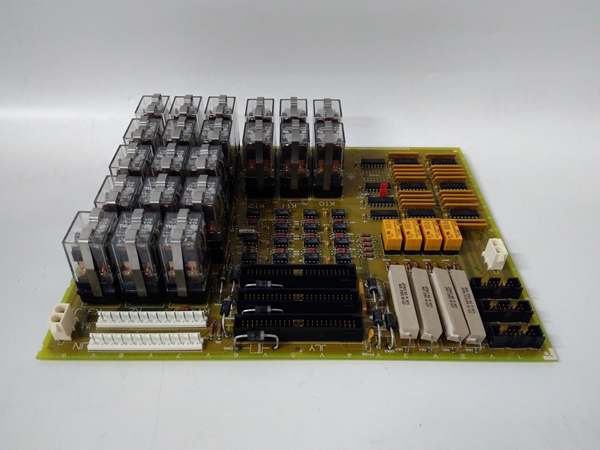
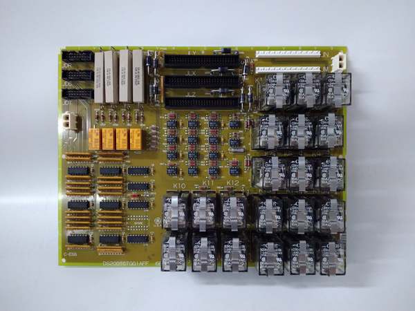
- Total Relays: 21 plug-in relays (K1–K21)
- Relay Mounting: Snap-in relays secured with metal straps
- Relay Configuration: Form-C (SPDT) relay configuration
- 50-Pin Connectors: 3 (JLY, JLX, JLZ)
- 12-Pin Connectors: 2 (JN, JM)
- Board Weight: 2.95 lbs (1.34 kg)
- Board Dimensions: 12 × 21 × 2.5 cm
- System Compatibility: SDCC Mark V System
- Module Category: PLC Module / Rack
- Instruction Manual: GEH-6153
- Configuration Method: Hardware-based relay configuration
- Revision Compatibility: First two revisions backwards compatible
- Industrial Rating: Designed for harsh industrial environments
- Operating Voltage: Compatible with AC (80-132 VAC) and DC (105-140 VDC) inputs

GE DS200TCTGG1AFF
The Real-World Problem It Solves
The Mark V gas turbine control system requires a dedicated trip mechanism capable of detecting fault conditions and initiating protective shutdowns with high reliability. The DS200TCTGG1AFF (Simplex Trip Board) addresses this need by providing a medium trip board with 21 independent relays that execute trip commands when abnormal conditions are detected. This board solves the challenge of integrating fault detection and trip logic into the Mark V architecture while maintaining isolation between control circuitry and field devices. The board functions as a safety layer that monitors critical operational parameters and executes protective shutdowns when necessary, preventing equipment damage and ensuring personnel safety. The 21 relays provide multiple trip paths for diverse fault conditions, including overspeed, overtemperature, vibration, and combustion instability. As a medium trip board, it interfaces with the SDCC (Startup and Digital Control Computer) Mark V System to receive trip signals and distribute them through the JLY, JLX, JLZ (50-pin) and JN, JM (12-pin) connectors to various shutdown circuits. The simple simplex design provides a non-redundant trip path for applications where dual redundancy is not required, while the plug-in relay architecture allows for easy maintenance and rapid replacement without removing the entire board. The normal PCB coating protects against environmental contaminants, and the industrial-grade construction ensures reliable operation under harsh turbine control cabinet conditions. Without this dedicated trip capability, the Mark V system would require external trip relays or complex safety-rated PLC integration, increasing complexity and potential failure points in critical safety functions.
Where you’ll typically find it:
- Mark V gas turbine control cabinets
- SDCC Mark V System rack assemblies
- Trip and shutdown logic circuits
- Overspeed protection systems
- Emergency shutdown networks
- Turbine safety instrumented systems (SIS)
- Combustion monitoring trip circuits
Bottom line: Medium simplex trip board—providing 21 relay-based trip paths for protective shutdowns in Mark V gas turbine control systems.
Hardware Architecture & Under-the-Hood Logic
The DS200TCTGG1AFF (Group One Revision A/F/F) is a Simplex Trip Board designed for integration into the GE Speedtronic Mark V control system as a medium trip board. The board houses 21 plug-in relays (K1-K21) arranged in a compact configuration, each secured with metal straps for vibration resistance and reliable contact engagement. The board’s primary function is to receive trip signals from the Mark V control system and execute protective shutdowns by activating relay contacts that interrupt control circuits or activate shutdown devices. The board receives control signals through the 50-pin connectors (JLY, JLX, JLZ) which typically connect to the SDCC or other Mark V control modules. Trip logic is processed externally by the Mark V control processors, and the TCTG board acts as the final element that physically opens or closes circuits to execute shutdowns. The 12-pin connectors (JN, JM) provide additional I/O connections for auxiliary trip functions or status feedback. Each relay is a Form-C (SPDT) configuration, providing both normally open and normally closed contacts for flexible trip circuit design—this allows fail-safe configurations where loss of power or relay failure results in a safe state (typically de-energized trip). The normal PCB coating protects components from moisture and contaminants, while the industrial-grade construction supports operation in harsh electrical environments with temperature fluctuations, vibration, and electrical noise. The revision history (A/F/F) indicates this is a mature design with functional and artwork refinements. The board operates as a simplex (non-redundant) device, meaning a single relay or board failure could compromise trip functionality—this configuration is typically used in applications where trip reliability requirements are met by the overall Mark V redundancy architecture rather than board-level redundancy.
Signal flow:
- Control system monitors turbine parameters via sensors
- SDCC Mark V System processes sensor data
- Fault conditions detected by control logic
- Trip signals generated by control processors
- Trip signals transmitted to TCTG board via JLY/JLX/JLZ connectors
- TCTG board receives trip activation commands
- Relay driver circuits energize specific relays (K1-K21)
- Relay coils energized based on trip command
- Form-C contacts switch from normal to tripped state
- Trip circuits opened/closed to execute shutdown
- Auxiliary functions activated via JN/JM connectors
- Shutdown devices (solenoid valves, fuel valves, actuators) de-energized
- Turbine coast-down initiated
- Status feedback transmitted through control system
- Trip events logged in system diagnostics
GE DS200TCTGG1AFF
Field Service Pitfalls: What Rookies Get Wrong
Replacing relays without proper power isolationWorking on live boards during relay replacement. I’ve seen technicians attempting relay swaps with power applied, creating electrical shock hazards and damaging relay driver circuits.
- Field Rule: Always disconnect power before relay replacement. Verify zero voltage with multimeter before handling relays. Follow LOTO (Lockout/Tagout) procedures. Never work on energized trip boards—electrical injury and equipment damage risk is high.
Forgetting to secure metal straps after relay installationLeaving relays unsecured with metal straps detached. I’ve seen technicians pressing relays into connectors but neglecting metal straps, causing vibration-induced relay failure.
- Field Rule: Secure metal straps after each relay installation. Verify both ends of the strap are clipped to connectors. Test strap tightness by gentle tug on relay. Never assume snap-in is sufficient—straps prevent vibration damage.
Mixing up JLY, JLX, JLZ connector assignmentsConnecting cables to wrong 50-pin connectors. I’ve seen technicians randomly plugging cables into any available connector, causing incorrect trip signal routing.
- Field Rule: Label all JLY, JLX, JLZ connectors during removal. Document which connector carries which trip signals. Use system wiring diagrams to verify assignments. Never rely on physical position alone—connector IDs matter.
Not verifying relay coil ratings during replacementInstalling incorrect relay types. I’ve seen technicians substituting relays with different coil voltages, preventing proper trip activation.
- Field Rule: Verify relay coil voltage matches board specifications. Check relay part numbers against OEM specifications. Use only GE-recommended relay replacements. Never assume any relay works—coil voltage must match.
Overlooking contact rating limitationsExceeding relay contact current ratings. I’ve seen technicians routing high-current trip circuits through relays rated for lower currents, causing contact welding.
- Field Rule: Verify load current does not exceed relay contact rating. Use contactors or larger relays for high-current trips. Check both resistive and inductive load ratings. Never exceed specifications—contact welding prevents trip execution.
Assuming all 21 relays are used in every applicationExpecting full relay utilization in all installations. I’ve seen technicians troubleshooting unused relays as faulty when they’re not configured in their specific application.
- Field Rule: Verify which relays are active for your application. Review trip logic diagrams for relay assignments. Test only configured relays. Never assume all 21 relays are active—application-specific configuration varies.
Neglecting to document trip event history before board replacementLosing diagnostic data when replacing boards. I’ve seen technicians removing boards without documenting LED states or trip event logs, losing valuable troubleshooting information.
- Field Rule: Document all LED indicators before board removal. Record trip event history from control system. Note any anomaly patterns. Never replace without documentation—historical data aids root cause analysis.
Incorrectly interpreting board revision compatibilityAssuming all revision levels are interchangeable. I’ve seen technicians attempting to install revision F boards in systems configured for revision A, causing incompatibility issues.
- Field Rule: Verify board revision matches system requirements. Check revision compatibility matrix. Only first two revisions are backwards compatible. Never assume any revision works—verify compatibility before installation.
Misrouting trip signals during reinstallationConnecting trip circuits to wrong relay outputs. I’ve seen technicians crossing wires between relays after board replacement, causing trips to activate on wrong fault conditions.
- Field Rule: Label all trip circuits before disconnection. Verify each wire destination before reconnection. Use wiring diagrams to confirm assignments. Never reconnect from memory—documentation prevents miswiring.
Forgetting to test trip functionality after board installationAssuming new boards work without verification. I’ve seen technicians installing replacement boards and returning the system to service without testing trip paths, leaving the turbine unprotected.
- Field Rule: Test all trip paths after board replacement. Simulate fault conditions to verify trip execution. Document test results for each relay. Never return to service without verification—untested trips compromise safety.
Ignoring vibration protection during installationOvertightening mounting screws or not securing boards properly. I’ve seen technicians creating stress on the board or allowing board movement, causing relay failures.
- Field Rule: Mount boards to specifications. Use proper torque on mounting hardware. Verify board is secure and level. Never overtighten—mechanical stress causes premature failure.
Commercial Availability & Pricing Note
Please note: The listed price is for reference only and is not binding. Final pricing and terms are subject to negotiation based on current market conditions and availability. As a critical safety component in Mark V gas turbine control systems, this Simplex Trip Board plays an essential role in turbine protection logic. The 21 plug-in relays are consumable components requiring periodic replacement throughout the board’s service life; spare relays should be maintained on-site for rapid replacement. The board’s simplex design (non-redundant) means that spare boards should be readily available for critical applications where downtime must be minimized. Refurbished and repaired units are commonly available, typically with 12-36 month warranties depending on vendor. When replacing, verify that the revision level (A/F/F) is compatible with your specific Mark V system configuration—not all revision levels are backwards compatible. The normal PCB coating provides environmental protection but does not offer conformal coating protection for highly corrosive environments; additional protection may be required in severe service conditions. Due to the safety-critical nature of trip functions, proper testing after installation is mandatory to ensure trip paths execute correctly before returning the turbine to service.


