
Description
Hard-Numbers: Technical Specifications
- Functional Acronym: TCRA (Turbine Control Relay Assembly)
- Functional Revision: A (Group One Mark V Series)
- Core Compatibility: Q11 and Q51 digital I/O cores
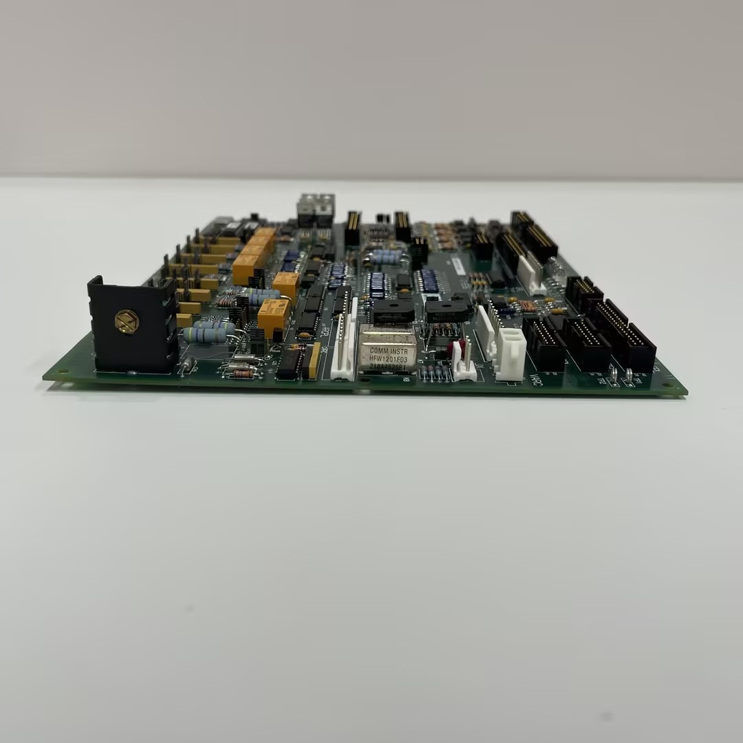
- Total Relays: 30 plug-in relays (K1–K30)
- Relay Contact Rating: 0.5 amp per relay
- Relay Type: Form-C (SPDT) relay configuration
- Q11 Core Relays: 4 relays active (blow-off valve control)
- Q51 Core Relays: 18 relays configurable as solenoid power source
- Core Location 5 Relays: 16 relays configurable as solenoid power source (both cores)
- 34-Pin Connectors: JOR, JOS, JOT (typically unused)
- 12-Pin Connectors: JS1, JS2, JS3, JS4, JS5, JS6, JS7, JS8 (output to DTBC/DTBD)
- Power Connectors: J19, J20 (120/240 V AC for ignition transformers)
- Control Connector: JO (signal input from TCDA/TCQE boards)
- Dimensions: 16.8 × 3.6 × 24.9 cm
- Weight: 0.55 kg
- PCB Coating: Normal coating (standard Mark V assembly)
- Instruction Manual: GEH-6153, GEH-6353
- Configuration Method: Hardware jumpers on DTBC/DTBD terminal boards
- Software Configuration: None (hardware-only configuration)

GE DS200TCQCG1A
The Real-World Problem It Solves
The Mark V LM control system requires dedicated relay output capabilities tailored to specific core functions within the digital I/O architecture. The DS200TCRAG2A (Relay Output Terminal Board) addresses this need by providing core-specific relay configurations optimized for Q11 and Q51 cores. This board solves the challenge of integrating relay-based control functions within the triple-redundant Mark V architecture while maintaining isolation between control logic and field devices. In the Q11 core, the board provides four relays specifically configured for gas manifold blow-off valve control, critical for gas turbine safety and combustion management. In the Q51 core, up to 18 relays can be configured as solenoid power sources, enabling direct power distribution to solenoid actuators without additional power supplies. The board’s hardware-level configuration (via DTBC/DTBD terminal board jumpers) allows flexible relay assignment between standard contact outputs and solenoid power functions, adapting to diverse application requirements without software changes. The TCRA board interfaces with TCDA boards via the JO connector to receive relay control signals from the control system, and distributes relay outputs to DTBC/DTBD terminal boards through JS1–JS8 connectors. Without this core-specific relay capability, the Mark V system would require generic relay boards with limited configurability or additional external power distribution hardware.
Where you’ll typically find it:
- Q11 core in Mark V LM digital I/O racks
- Q51 core in Mark V LM digital I/O racks
- Gas manifold blow-off valve control circuits
- Solenoid power distribution systems
- Ignition transformer control circuits
- Digital I/O core relay output assemblies
Bottom line: Core-specific relay output board—providing Q11/Q51 relay configurations with solenoid power capability and gas manifold blow-off valve control for Mark V LM turbine control systems.
Hardware Architecture & Under-the-Hood Logic
The DS200TCRAG2A (Group One Revision A) is the Relay Output Terminal Board designed specifically for Q11 and Q51 cores within the Mark V LM digital I/O architecture. The board houses 30 plug-in relays (K1–K30) arranged in a compact configuration, with relay utilization varying based on core location. In the Q11 core (core location 4), only four relays are active and connected to the TCQE board via the JO connector; these relays typically control gas manifold blow-off valves. In the Q51 core (core location 4), the first 18 relays can be configured as solenoid power sources through hardware jumpers on the DTBC terminal board. For TCRA boards in core location 5 (both Q11 and Q51 cores), the first 16 relays can be configured as solenoid power sources via DTBD terminal board jumpers. The board receives relay control signals from TCDA boards through the JO connector; these signals originate from the control system processors (CSP) and are transmitted via COREBUS, IO Engines, STCA, and IONET. The board’s relays provide Form-C (SPDT) contact outputs with 0.5 amp rating, suitable for low-power control applications. Power connections J19 and J20 receive 120/240 V AC from the DTBD board in one core, typically used for ignition transformers; position 5 of these connectors can wet two extra contact outputs (#47 and #48). The relay outputs are distributed to DTBC and DTBD terminal boards through connectors JS1 through JS8. Hardware configuration for relay power sources or solenoid conversion occurs at the terminal board level (DTBC/DTBD jumpers), not on the TCRA board itself. The JOR, JOS, and JOT connectors are present but typically unused in standard TCRA applications.
Signal flow:
- Control signals from CSP processors generated by turbine control logic
- Signals transmitted via COREBUS to IO Engines
- IO Engines communicate with STCA boards
- STCA boards transmit signals via IONET
- TCDA boards receive signals from STCA via IONET
- TCDA boards write relay control signals via JO connector
- TCRA board receives signals through JO connector
- For Q11 core (location 4): TCQE board provides signals via JO connector
- Relay driver circuits process control signals
- Relay coils energized/de-energized based on control logic
- K1–K30 relays switch Form-C contacts
- Relay outputs routed to JS1–JS8 connectors
- JS1–JS8 connectors connect to DTBC/DTBD terminal boards
- DTBC/DTBD boards distribute relay contacts to field devices
- J19/J20 connectors receive 120/240 V AC from DTBD board
- Ignition transformers powered via J19/J20 connections
- Hardware jumpers on DTBC/DTBD configure relay modes
- Position 5 of J19/J20 can wet outputs #47 and #48
- Solenoid power sources configured via DTBC/DTBD jumpers
- Contact isolation maintained between control and field sides
GE DS200TCQCG1A
Field Service Pitfalls: What Rookies Get Wrong
Confusing Q11 and Q51 core relay configurationsNot understanding core-specific relay assignments. I’ve seen technicians expecting all 30 relays to work in any core, not realizing Q11 core only uses 4 relays.
- Field Rule: Verify core location before troubleshooting. Q11 core (location 4) uses only 4 relays for blow-off valves. Q51 core can use up to 18 relays as solenoid power sources. Never assume uniform configuration—core location determines relay count.
Misconfiguring solenoid power jumpers on DTBC/DTBDSetting wrong jumper positions for solenoid power. I’ve seen technicians configuring jumpers on TCRA board, when solenoid power configuration occurs on DTBC/DTBD terminal boards.
- Field Rule: Configure solenoid power sources via DTBC/DTBD jumpers, not on TCRA board. First 18 relays (location 4) or first 16 relays (location 5) can become power sources. Verify jumper settings match application requirements. Never configure TCRA jumpers for solenoid power—configuration is terminal board-level.
Forgetting JO connector signal source varies by coreIncorrectly identifying JO connector signal source. I’ve seen technicians expecting JO to always connect to TCDA, not realizing Q11 core (location 4) connects to TCQE.
- Field Rule: Verify JO connector signal source based on core location. Q11/Q51/Q21 cores (location 5) receive TCDA signals via JO. Q11 core (location 4) receives TCQE signals via JO. Never assume JO connects to TCDA—signal source varies by core.
Overlooking J19/J20 ignition transformer powerNot utilizing 120/240 V AC power connections. I’ve seen technicians leaving J19/J20 disconnected, causing ignition transformer failures.
- Field Rule: Verify J19/J20 connections for ignition transformer applications. DTBD board provides 120/240 V AC to these connectors. Position 5 can wet outputs #47 and #48. Never leave J19/J20 disconnected when ignition transformers are present—check power requirements.
Mixing up JS1–JS8 connector assignmentsConnecting relays to wrong JS connectors. I’ve seen technicians randomly connecting to JS connectors without following terminal board wiring diagrams.
- Field Rule: Follow JS connector wiring diagrams for DTBC/DTBD boards. JS1–JS8 connect relay outputs to specific terminal board locations. Verify each relay’s destination before connecting. Never arbitrarily connect—follow wiring schematics.
Assuming all 30 relays are available in all coresExpecting full relay complement in every core location. I’ve seen technicians trying to use unavailable relays in Q11 core (location 4).
- Field Rule: Understand relay availability by core location. Core location 4 (Q11): only 4 relays active. Core location 4 (Q51): up to 18 relays available. Core location 5 (both cores): up to 16 relays configurable. Never assume all 30 relays are usable—check core-specific limits.
Neglecting relay contact rating limitsExceeding 0.5 amp contact rating. I’ve seen technicians driving high-current loads directly, causing contact welding and failure.
- Field Rule: Verify load current does not exceed 0.5 amp per contact. Use intermediate relays or contactors for higher current. Calculate inrush current for inductive loads. Never exceed contact rating—check load specifications first.
Skipping hardware jumper documentation during installationNot documenting DTBC/DTBD jumper settings. I’ve seen technicians configuring jumpers without documentation, causing confusion during future maintenance.
- Field Rule: Document all DTBC/DTBD jumper settings during installation. Record which relays are configured as solenoid power sources. Label jumper configurations clearly. Never install without documentation—proper records prevent future errors.
Forgetting to verify Form-C contact usageNot utilizing both NO and NC contacts appropriately. I’ve seen technicians using only NO contacts, missing NC contact functionality for fail-safe applications.
- Field Rule: Verify Form-C contact usage matches application requirements. Use normally open (NO) for standard actuation. Use normally closed (NC) for fail-safe applications. Document contact assignments. Never ignore NC contacts—they provide fail-safe capabilities.
Confusing TCRA with TCRA-CC board differencesMixing up TCRA and TCRA-CC board functions. I’ve seen technicians treating these boards as identical, not understanding TCRA-CC has different capabilities.
- Field Rule: Clearly distinguish TCRA from TCRA-CC boards. TCRA is Relay Output Terminal Board for Q11/Q51 cores. TCRA-CC has different functionality and applications. Verify board part number matches system requirements. Never assume interchangeability—check board designation.
Commercial Availability & Pricing Note
Please note: The listed price is for reference only and is not binding. Final pricing and terms are subject to negotiation based on current market conditions and availability. As a core-specific Relay Output Terminal Board designed for Q11 and Q51 cores within the Mark V LM architecture, availability may be limited depending on core configuration requirements. The board’s functionality varies significantly based on core location (4 or 5) and core type (Q11 vs Q51), requiring careful verification of application-specific relay configurations. This board does not support software configuration; all relay functions are configured via hardware jumpers on DTBC/DTBD terminal boards. Due to the core-specific design, ensure compatibility with the target core configuration before procurement. The 30 plug-in relays are consumable components with 0.5 amp contact ratings requiring periodic replacement throughout the board’s lifecycle. Refurbished units with replaced relays may be commonly available for legacy Mark V LM systems.


