
Description
Hard-Numbers: Technical Specifications
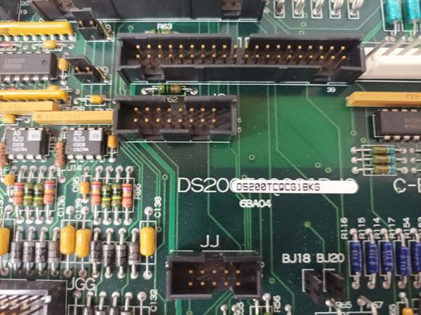
- Functional Acronym: TCQC (Turbine Control Quadrature Card)
- Functional Revision 1: B (First functional revision)
- Functional Revision 2: K (Second functional revision)
- Artwork Revision: G (PCB artwork revision)
- Core Function: RST overflow handling and analog I/O expansion
- Analog Input Channels: 16 channels (0-5V input range)
- DAC Channels: 2 channels for digital-to-analog conversion
- Servo Output Current Range: ±240 mA (maximum with jumper configuration)
- Hardware Jumpers: 24 configuration jumpers (BJ1-BJ24, plus JP38-JP39)
- 40-Pin Connectors: 3 (JFF, JE, 6PL)
- 34-Pin Connectors: 3
- 16-Pin Connectors: 1 (JC)
- Signal Types: LVDT, LVDR, magnetic pickup, TTL pulse rate, mA input
- Power Requirements: +5 V DC (primary), ±15 V DC (proximity transducers)
- Dimensions: 28 × 21.2 × 3.5 cm
- Weight: 0.46 kg (13.60 lbs)
- PCB Coating: Normal coating (non-conformal)
- Operating Temperature: -40°C to +85°C
- Storage Temperature: -55°C to +125°C
- Protection: Voltage suppression and transient protection circuits
- Manual: GEH-6153 (Analog IO Expander Board Data Sheet)

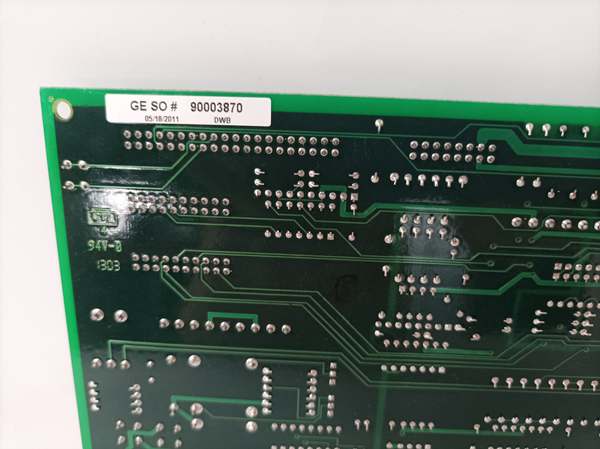
GE DS200TCQCG1BKG
The Real-World Problem It Solves
The Mark V control system in LM2500 aeroderivative gas turbine applications requires extensive analog signal processing capabilities beyond the base I/O core capacity. The DS200TCQCG1BKG (RST Overflow Board) addresses this need by providing additional analog input/output expansion, specialized signal conditioning for LVDT/LVDR position sensors, pulse rate scaling for speed measurement, and megawatt transducer signal processing. This board solves the challenge of interfacing multiple sensor types—linear variable differential transformers (LVDT), rotary variable differential transformers (LVDR), magnetic speed pickups, and TTL pulse rate sensors—within a single expansion module. It provides scaling and conditioning for high-pressure shaft speed signals, liquid fuel flow measurements, and generator power monitoring (megawatt transducer). The board also handles RST overflow functions, managing signal routing between terminal boards (PTBA, QTBA, TBQB, TCQE) and control boards (TCQA, STCA). Without this expansion capability, the Mark V system would lack sufficient analog channels and specialized conditioning circuits, requiring additional hardware or limiting sensor integration capabilities.
Where you’ll typically find it:
- Mark V LM2500 control racks
- I/O core expansion slots
- RST signal overflow handling applications
- Turbine speed measurement systems
- Actuator position feedback systems
- Generator power monitoring circuits
Bottom line: Analog I/O expansion board—providing LVDT/LVDR excitation, pulse rate scaling, megawatt transducer conditioning, and RST overflow management for enhanced turbine control signal processing.
Hardware Architecture & Under-the-Hood Logic
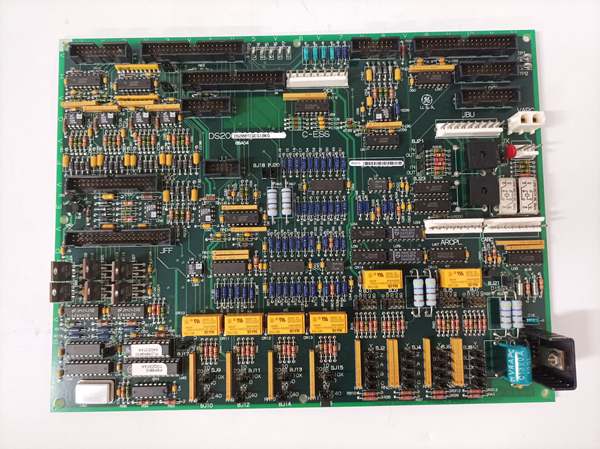
The DS200TCQCG1BKG (Functional Revision B/K, Artwork Revision G) is the RST Overflow Board and Analog IO Expander Board for the Mark V LM2500 control system, serving as the signal conditioning and expansion interface for various analog sensor types. The board receives analog signals from multiple terminal boards (PTBA, QTBA, TBQB, TCQE) through its input connectors and processes these signals through conditioning circuits. For LVDT and LVDR sensors, the board provides excitation signals and conditions the position feedback outputs. Pulse rate inputs from magnetic speed sensors and TTL-type sensors are scaled and conditioned, then routed to the TCQA board for further processing via the JE connector. The megawatt transducer mA input is scaled and conditioned, then transmitted to the STCA board via the 19PL connector. The board includes 24 hardware jumpers (BJ1-BJ24) that configure various parameters: the first 16 jumpers set servo output current ranges (even-numbered for feedback scaling, odd-numbered for source output resistance), jumpers 25-36 provide extended feedback scaling for servos 1-4 (±240 mA maximum), and jumpers JP38-JP39 set magnetic pickup gain for liquid fuel flow signals. The board communicates with TCQA and STCA boards via the JE connector and includes IONET termination functions. Diagnostic and test features include RS232 port configuration (BJ17), stall timer enable (BJ21), and factory test oscillator (BJ22). The board also includes voltage-limiting components (rectifiers, capacitors, diodes) and heat sinks for thermal management.
Signal flow:
- Analog signals from terminal boards (PTBA, QTBA, TBQB) enter through input connectors
- LVDT/LVDR excitation signals generated and transmitted to sensors
- LVDT/LVDR position feedback signals received and conditioned
- Pulse rate signals from TCQE board received via JJ connector
- Magnetic pickup pulse rate signals received via JH connector
- TTL pulse rate signals from TBQB terminal board received via JH connector
- Additional magnetic pickup signals from QTBA board received via JGG connector
- Megawatt transducer mA input received and scaled
- Pulse rate scaling circuits condition speed signals
- High-pressure shaft speed signals routed to TCQA via JE connector
- Liquid fuel flow signals scaled and processed
- Megawatt transducer signals transmitted to STCA via 19PL connector
- Generator and line signals communicated with STCA via JE connector
- Servo output circuits generate control signals (±240 mA maximum)
- Hardware jumpers configure current ranges, scaling, and gain
- IONET termination functions handle network communications
- Voltage suppression circuits protect against transients
- Heat sinks dissipate power from output circuits
- Power conditioning provides +5 V DC and ±15 V DC supplies
- Diagnostic circuits monitor signal integrity and board status
GE DS200TCQCG1BKG
Field Service Pitfalls: What Rookies Get Wrong
Improper jumper configuration causes servo output errorsIncorrect jumper settings for servo outputs. I’ve seen technicians failing to configure the first 16 jumpers correctly, causing wrong current ranges and erratic servo operation.
- Field Rule: Verify jumper configuration before installation. Jumpers 1-16 configure servo output current: even-numbered for feedback scaling, odd-numbered for source resistance. Document all jumper settings. Never assume factory-default configuration matches your application—configure jumpers per specific requirements.
Skipping magnetic pickup gain adjustment causes speed measurement errorsNot setting JP38/JP39 for liquid fuel flow signals. I’ve seen technicians leaving these jumpers at default settings, causing inaccurate flow measurements.
- Field Rule: Configure magnetic pickup gain jumpers (JP38/JP39) for liquid fuel flow applications. Verify gain settings match sensor specifications. Test speed measurement accuracy after configuration. Never ignore these jumpers—proper gain ensures accurate flow measurement.
Confusing PTBA and QTBA terminal board signals causes duplicate inputsLanding signals on both PTBA and QTBA boards. I’ve seen technicians routing the same signals to both terminal boards, causing conflicts and unreliable readings.
- Field Rule: Verify signal routing between PTBA and QTBA terminal boards. Some signals can be landed on either board, but not both. If signals are on PTBA, corresponding QTBA terminal points are unavailable. Never duplicate signal routing—choose one terminal board per signal.
Overlooking proximity transducer voltage limits causes sensor damageExceeding ±15 V supply limits. I’ve seen technicians failing to set BJ18/BJ20 to limit P15/N15 supplies, damaging sensitive proximity transducers.
- Field Rule: Configure BJ18 and BJ20 to limit ±15 V supplies to proximity transducers. Verify voltage levels before connecting sensors. Measure supply voltage at transducer connector. Never apply unregulated supply—always use limited voltage for proximity sensors.
Incorrect connector ID mapping causes signal misroutingMixing up connector IDs (JFF, JE, 6PL, JC). I’ve seen technicians connecting cables to wrong connectors, causing signal routing failures.
- Field Rule: Verify connector ID mapping before making connections. JFF, JE, and 6PL are 40-pin connectors; JC is 16-pin. Each connector has specific signal functions. Refer to connector pinout diagrams. Never assume connector interchangeability—verify each connector’s purpose.
Forgetting to test stall timer causes servo lockup failureNot verifying stall timer function. I’ve seen technicians enabling BJ21 without testing stall timer, causing servo motors to lock up during normal operation.
- Field Rule: Test stall timer functionality after enabling BJ21. Verify stall timer triggers at correct current thresholds. Test servo response during stall conditions. Never enable stall timer without verification—untested stall protection can cause unexpected shutdowns.
Improper LVDT excitation causes position feedback errorsIncorrect LVDT excitation settings. I’ve seen technicians using wrong excitation voltage or frequency, causing inaccurate position measurements.
- Field Rule: Verify LVDT excitation parameters match sensor specifications. Check excitation voltage and frequency at LVDT connector. Test position feedback accuracy across full range. Never assume generic excitation works—match excitation to specific LVDT requirements.
Skipping IONET termination causes communication failuresNot verifying IONET termination. I’ve seen technicians installing TCQC boards without checking IONET termination, causing network communication errors.
- Field Rule: Verify IONET termination configuration. Check if optional <21> is installed and where termination should be. Confirm termination matches system requirements. Never skip termination verification—improper termination causes network failures.
Neglecting RS232 port configuration prevents diagnostic accessNot configuring RS232 port for card tests. I’ve seen technicians leaving BJ17 unset, preventing RS232 diagnostic communication.
- Field Rule: Configure BJ17 to enable RS232 port for card tests. Verify RS232 communication works with diagnostic equipment. Test port before relying on diagnostics. Never leave RS232 port unconfigured—diagnostic access is essential for troubleshooting.
Ignoring heat sink clearance causes thermal issuesBlocking heat sink airflow. I’ve seen technicians installing boards with insufficient clearance for heat sinks, causing overheating and premature failure.
- Field Rule: Ensure adequate heat sink clearance and airflow. Keep adjacent components away from heat sinks. Verify cabinet ventilation meets requirements. Never obstruct heat sinks—thermal management is critical for reliability.
Commercial Availability & Pricing Note
Please note: The listed price is for reference only and is not binding. Final pricing and terms are subject to negotiation based on current market conditions and availability. As a specialized RST Overflow Board with multiple functional revisions (B/K) and artwork revision (G), availability may be limited and lead times extended. This board is considered a legacy product with discontinued OEM support, requiring careful verification of compatibility with Mark V LM2500 system configurations. Proper jumper configuration and terminal board signal routing are essential for reliable operation. Due to obsolete status, refurbished or reconditioned units may be the primary availability option.


