
Description
Hard-Numbers: Technical Specifications
- Functional Acronym: TCQC (Turbine Control Quadrature Card)
- Board Variant: G1 variant (specific hardware configuration)
- Revision: A (Board Revision A)
- Core Function: Quadrature counter processing and position accumulation
- Input Signal Types: Quadrature encoder signals (A, B channels), optional index pulse (Z channel)
- Signal Levels: Compatible with TTL, differential, or voltage-level encoder signals
- Channels: Multiple quadrature counter channels (typically 2-4 channels)
- Counter Resolution: High-resolution position counting (up to 16-bit or higher)
- Counter Type: Up/down counter with direction detection
- Direction Detection: Automatic direction sensing based on A/B phase relationship
- Index Pulse: Index pulse (Z channel) detection for position reference and counter reset
- Speed Measurement: Speed calculation from count rate
- Preset Capability: Counter preset/load capability for position referencing
- Latch Capability: Count latch for synchronous reading
- Diagnostic Features: Signal loss detection, counter overflow/underflow detection
- LED Indicators: Multiple LED indicators for channel status, signal presence, counter state
- Power Requirements: Typically 24 V DC from control system power supply
- Dimensions: Standard Mark V board form factor (typically 3″ H × 11.5″ W)
- PCB Coating: Normal coating (non-conformal)
- Manual: GEH-6236 (Turbine Control Quadrature Card Manual)

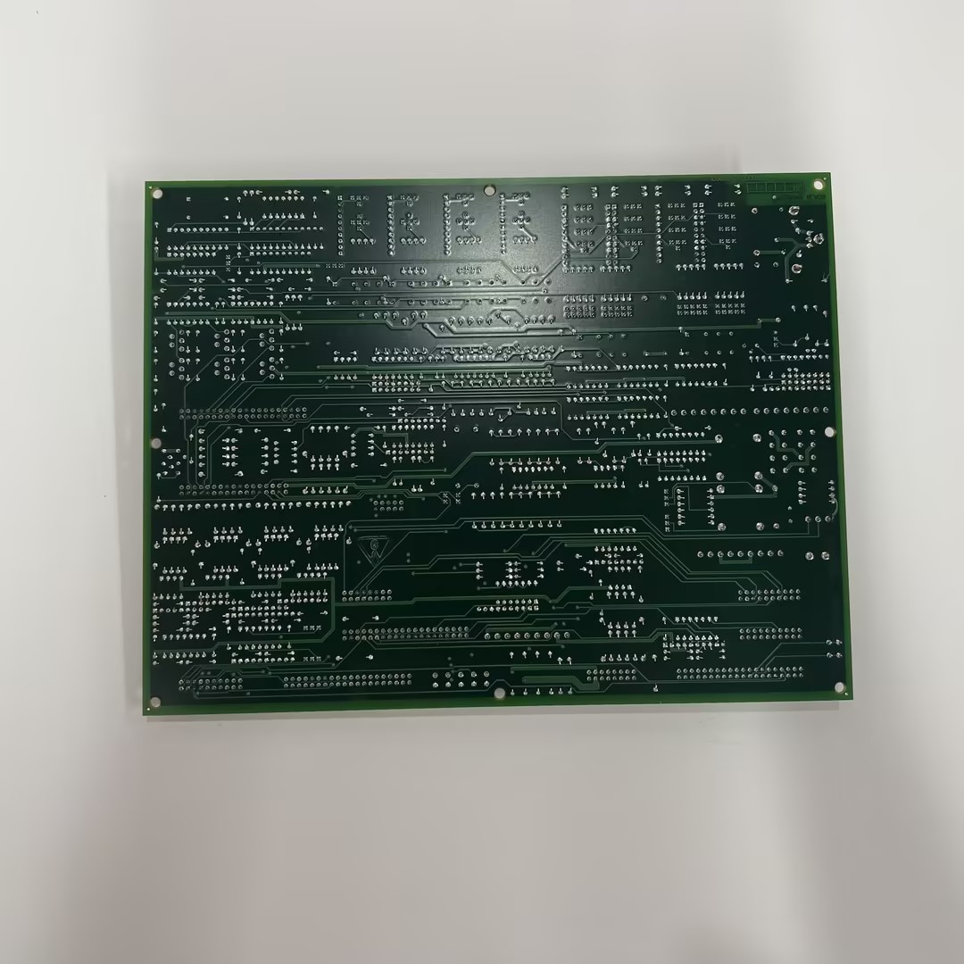
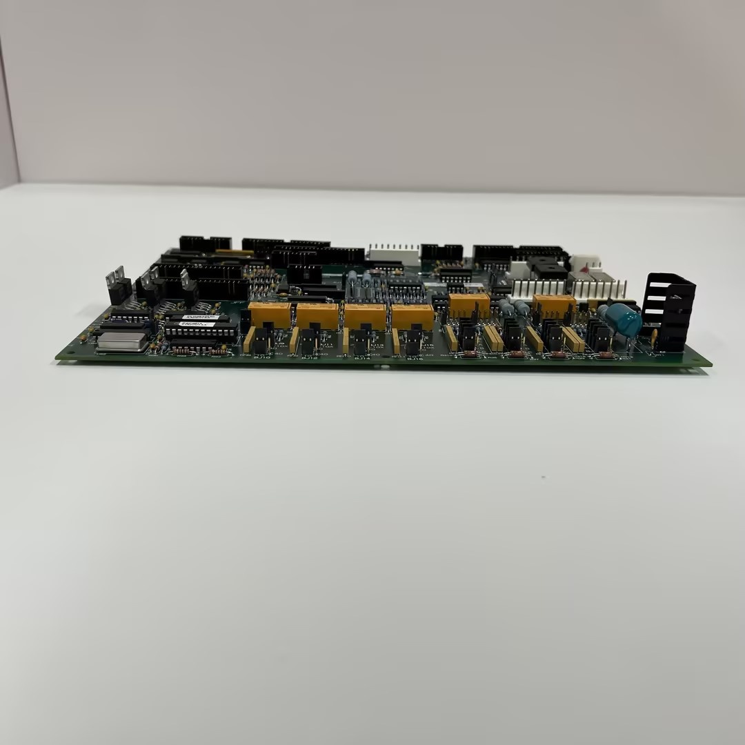
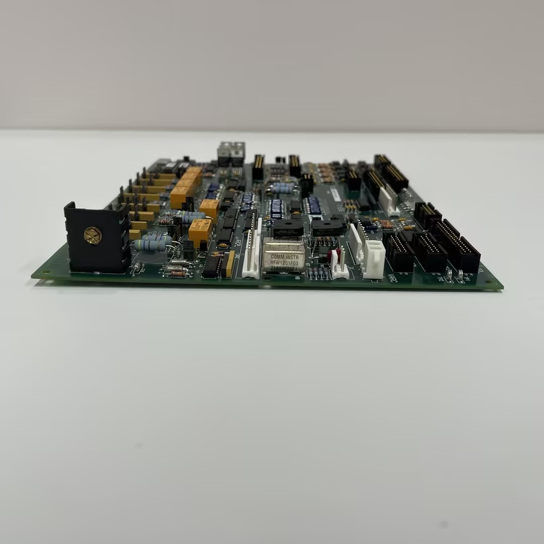
GE DS200TCQCG1A

The Real-World Problem It Solves
The Mark V control system in turbine applications requires high-resolution position counting and speed measurement from quadrature encoders to control turbine speed, governor operation, and actuator positioning with precision. The DS200TCQCG1A (Turbine Control Quadrature Card – G1 Variant, Revision A) provides this critical quadrature counter processing capability, serving as the dedicated position counting interface for quadrature encoder signals. Unlike the TCQA board which focuses on signal conditioning and decoding, the TCQC card focuses on high-resolution position counting, accumulating encoder counts to provide precise position data over multiple revolutions. The board receives quadrature signals (A and B channels) from encoder interfaces, processes these signals through conditioning circuits, and uses high-resolution up/down counters to accumulate position counts based on the quadrature waveform. The counters automatically detect direction based on the A/B phase relationship, incrementing or decrementing accordingly. The board calculates speed based on the rate of count change over time and provides position and speed data to Mark V control processors for use in governor control, speed regulation, and actuator positioning. Without this card, the Mark V system would lack high-resolution position counting capability, limiting control accuracy and preventing precise multi-revolution position tracking.
Where you’ll typically find it:
- Control racks in Mark V control cabinets
- Turbine control systems requiring high-resolution position counting
- Multi-revolution position tracking applications
- Actuator positioning systems with quadrature encoder feedback
- Generator shaft position monitoring with extended range
- Applications requiring precise position counting and speed measurement
Bottom line: Quadrature counter processing card—providing high-resolution position counting, direction detection, speed calculation, and multi-revolution position tracking for precise turbine control feedback.
Hardware Architecture & Under-the-Hood Logic
The DS200TCQCG1A (G1 Variant, Revision A) is the Turbine Control Quadrature Card for the Mark V control system, serving as the dedicated quadrature counter processing interface. The board provides multiple counter channels for processing quadrature encoder signals with high-resolution counting capability. Each counter channel receives quadrature encoder signals (A and B channels) and optional index pulse (Z channel) through input connectors and protection circuits. The input signals pass through signal conditioning circuits that provide filtering, threshold detection, and noise immunity features. The conditioned quadrature signals are then processed by quadrature decoder logic that determines the direction of rotation based on the A/B phase relationship and generates count increment/decrement signals accordingly. High-resolution up/down counters accumulate these count increments to provide position data with extended range for multi-revolution tracking. Index pulse detection circuits detect the Z channel signal and can be used to reset counters to a known reference position or to mark revolution boundaries. Speed calculation circuits compute speed based on the rate of count change over time, providing accurate speed feedback. The board includes counter preset/load capability for establishing position references and latch capability for synchronous reading of counter values to avoid read-while-write issues. Diagnostic circuits monitor signal integrity, detect counter overflow/underflow conditions, identify signal loss or cable faults, and communicate status information through LED indicators and system interfaces.
Signal flow:
- Quadrature encoder signals (A, B channels) enter TCQC through input connectors
- Index pulse (Z channel) enters through dedicated input
- Input protection circuits provide overvoltage and transient protection
- Signal conditioning circuits filter and threshold encoder signals
- Quadrature decoder logic determines direction and generates count pulses
- Direction detection identifies rotation direction (CW/CCW)
- High-resolution up/down counters accumulate count increments/decrements
- Index pulse detection provides position reference for counter reset
- Counter preset/load circuits establish reference positions
- Count latch circuits provide synchronous counter reading
- Speed calculation circuits compute speed from count rate
- Position and speed data are formatted for transmission to control processors
- Diagnostic circuits monitor signal integrity and counter status
- Overflow/underflow detection prevents count errors
- LED indicators display channel status, signal presence, and counter state
GE DS200TCQCG1A
Field Service Pitfalls: What Rookies Get Wrong
Confusing TCQC with TCQA causes functional confusionMixing up TCQC and TCQA boards. I’ve seen technicians treating TCQC (counter card) as TCQA (signal conditioning board), causing system configuration errors.
- Field Rule: Clearly distinguish TCQC vs. TCQA. TCQC is Turbine Control Quadrature Card—focuses on high-resolution position counting. TCQA is Turbine Control Quadrature Board—focuses on signal conditioning and decoding. Check board label for “TCQC” designation. Never assume quadrature boards are identical—TCQC provides counter processing.
Forgetting to verify counter resolution settings causes accuracy issuesNot configuring counter resolution parameters. I’ve seen technicians using default resolution settings, causing position measurement errors or insufficient range.
- Field Rule: Configure counter resolution parameters after installation. Verify counter resolution matches encoder specifications (LPR or CPR). Check that counter range supports required position range. Test counter accuracy across full range. Never assume default resolution is correct—configure for application requirements.
Skipping index pulse counter reset causes position driftNot configuring index pulse reset. I’ve seen technicians installing TCQC cards without configuring index pulse reset, causing position drift over multiple revolutions.
- Field Rule: Configure index pulse counter reset after installation. Verify index pulse detection works correctly. Configure counter reset on index pulse if required for position reference. Test counter reset functionality during rotation. Never assume counter stays accurate without reset—configure index reset for position reference.
Neglecting counter overflow/underflow monitoring causes count errorsNot monitoring counter limits. I’ve seen technicians installing TCQC cards without setting up overflow/underflow monitoring, causing count errors beyond counter range.
- Field Rule: Configure counter overflow/underflow monitoring. Verify counter range matches application requirements. Set up overflow/underflow detection and alarms. Test counter behavior at range limits. Never assume counter has infinite range—monitor limits to prevent errors.
Improper counter preset causes position reference errorsIncorrect counter preset values. I’ve seen technicians setting wrong counter preset values, causing incorrect position references.
- Field Rule: Verify counter preset values after installation. Check that preset values match application requirements. Document preset configuration. Test counter preset/load functionality. Never assume preset values are correct—verify preset configuration.
Overlooking synchronous count latch causes read errorsNot using count latch for reading. I’ve seen technicians reading counter values directly without latching, causing read-while-write errors and inconsistent readings.
- Field Rule: Use synchronous count latch for counter reading. Always latch counter value before reading to avoid read-while-write errors. Verify latch operation works correctly. Never read counter directly without latching—use latch for consistent readings.
Skipping direction detection verification causes direction errorsNot verifying direction detection. I’ve seen technicians installing TCQC cards without checking direction detection, causing incorrect direction sensing.
- Field Rule: Verify direction detection after installation. Test rotation in both directions and verify counter increments/decrements correctly. Check that direction flag outputs match rotation direction. Never assume direction detection is correct—verify bidirectional operation.
Forgetting to calibrate speed calculation causes measurement errorsNot calibrating speed calculation parameters. I’ve seen technicians using default speed calculation settings, causing speed measurement errors.
- Field Rule: Calibrate speed calculation after installation. Verify speed calculation accuracy with known reference speeds. Check speed measurement across operating range. Document speed calibration parameters. Never assume speed calculation is accurate—calibrate before placing in service.
Improper encoder grounding causes signal noise and count errorsIncorrect encoder grounding. I’ve seen technicians grounding encoders incorrectly, introducing noise that causes count errors.
- Field Rule: Follow proper encoder grounding procedures. Use differential encoder connections for noise immunity. Verify encoder shield grounding follows Mark V specifications. Avoid ground loops that affect count accuracy. Never improvise encoder grounding—improper grounding causes count errors.
Skipping counter diagnostic verification causes missed faultsNot verifying counter diagnostics. I’ve seen technicians installing TCQC cards without testing diagnostic features, missing counter fault information.
- Field Rule: Verify counter diagnostic features after installation. Test signal loss detection functionality. Verify overflow/underflow detection works correctly. Check diagnostic LED indications. Never assume diagnostics work—test diagnostic features before placing in service.
Commercial Availability & Pricing Note
Please note: The listed price is for reference only and is not binding. Final pricing and terms are subject to negotiation based on current market conditions and availability. As a specialized quadrature counter processing component, availability may be limited and lead times extended. TCQC boards require compatibility verification with encoder types, resolution requirements, and application-specific configurations. Proper encoder selection and installation are essential for reliable operation.


