
Description
Hard-Numbers: Technical Specifications
- Functional Acronym: TCPS (Turbine Control Power Supply Board)
- Board Variant: G1 variant (specific hardware configuration)
- Revision: A (Board Revision A)
- Core Function: Power distribution and conditioning for control system
- Input Power: Typically 125 V DC or 250 V DC input from external power sources
- Output Voltages: Multiple regulated DC output voltages (typically +5 V DC, ±15 V DC, +24 V DC)
- Power Capacity: Sufficient power capacity for multiple control boards
- Voltage Regulation: Precision voltage regulation for sensitive control electronics
- Current Limiting: Current limiting and protection features
- Overvoltage Protection: Overvoltage protection for output circuits
- Undervoltage Detection: Undervoltage monitoring and detection
- Power Sequencing: Controlled power sequencing for system startup
- Isolation: Electrical isolation between input and output circuits
- Diagnostic Features: Power status monitoring and fault detection
- LED Indicators: Multiple LED indicators for power status, faults, output voltages
- Dimensions: Standard Mark V board form factor (typically 3″ H × 11.5″ W)
- PCB Coating: Normal coating (non-conformal)
- Manual: GEH-6230 (Turbine Control Power Supply Board Manual)

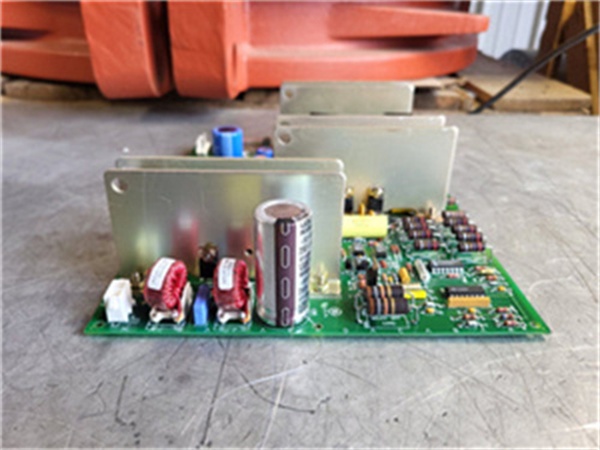
GE DS200TCPSG1A
The Real-World Problem It Solves
The Mark V control system requires reliable, conditioned power distribution to operate all control boards, processors, interface boards, and associated electronics consistently and safely. The DS200TCPSG1A (Turbine Control Power Supply Board – G1 Variant, Revision A) provides this critical power distribution and conditioning capability, converting external power sources into multiple regulated DC voltages required by various Mark V control system components. External power sources (typically 125 V DC or 250 V DC) are converted to precise, stable DC voltages (+5 V DC for logic circuits, ±15 V DC for analog circuits, +24 V DC for field devices and relays) that power control boards, processors, and interface boards throughout the Mark V system. The board provides voltage regulation to maintain output voltages within tight tolerances, current limiting to protect against overloads, and overvoltage/undervoltage protection to safeguard sensitive electronics. The G1 variant indicates a specific hardware configuration optimized for particular power distribution requirements. Without this board, the Mark V control system would lack conditioned power distribution, leading to unstable operation, component damage from voltage transients, or complete system failure.
Where you’ll typically find it:
- Power supply racks in Mark V control cabinets
- Turbine control systems requiring conditioned power distribution
- Power supply distribution assemblies in control rooms
- Power generation facilities with Mark V control systems
- Combined cycle plants requiring reliable control system power
- Applications requiring G1-specific power distribution capabilities
Bottom line: Power supply distribution board—providing regulated, conditioned power to Mark V control system components with voltage regulation, current limiting, and protection features.
Hardware Architecture & Under-the-Hood Logic
The DS200TCPSG1A (G1 Variant, Revision A) is the Turbine Control Power Supply Board for the Mark V control system, serving as the power distribution and conditioning center for control system components. The board receives input power from external DC power sources (typically 125 V DC or 250 V DC) through input connectors and protection circuits. The input power passes through input filtering, surge protection, and isolation circuits to remove transients and provide electrical isolation from the external source. The filtered input power is then routed to multiple DC-to-DC converter modules that generate the regulated output voltages required by Mark V control system components: +5 V DC for digital logic circuits, +15 V DC and -15 V DC for analog signal processing, and +24 V DC for field device power, relay drivers, and output circuits. Each output voltage is individually regulated to maintain tight tolerances, with current limiting circuits protecting against overloads. Overvoltage protection circuits clamp output voltages to safe levels in case of regulator failures, while undervoltage detection circuits monitor output voltages and signal low voltage conditions. The board includes power sequencing capabilities to ensure controlled startup of control system components. Diagnostic circuits monitor power status, output voltages, currents, and fault conditions, providing status information through LED indicators and communication interfaces to system monitoring functions.
Signal flow:
- Input power from external DC source enters TCPS through input connectors
- Input protection circuits provide overcurrent protection and transient suppression
- Input filtering circuits remove noise and ripple from input power
- Isolation circuits provide electrical separation from external power source
- Filtered input power is distributed to DC-to-DC converter modules
- +5 V DC converter generates regulated +5 V DC for digital logic circuits
- +15 V DC converter generates regulated +15 V DC for analog circuits
- -15 V DC converter generates regulated -15 V DC for analog circuits
- +24 V DC converter generates regulated +24 V DC for field devices
- Each output has current limiting circuits to protect against overloads
- Overvoltage protection circuits clamp output voltages to safe levels
- Undervoltage detection circuits monitor output voltages
- Power sequencing circuits control startup order of output voltages
- Diagnostic circuits monitor power status and fault conditions
- LED indicators display power status, output voltages, and fault conditions
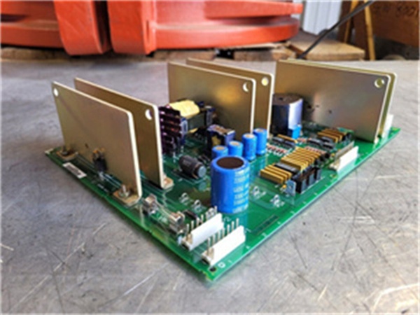
GE DS200TCPSG1A
Field Service Pitfalls: What Rookies Get Wrong
Overlooking input power requirements causes TCPS failuresConnecting wrong input voltage. I’ve seen technicians applying incorrect input voltage to TCPS boards, causing immediate board failure or damaged components.
- Field Rule: Verify input power requirements before connection. Check that input voltage matches TCPS specification (125 V DC or 250 V DC). Verify input polarity is correct. Measure input voltage before connecting to TCPS. Never assume input power is correct—verify voltage and polarity before connection.
Neglecting output load balancing causes voltage instabilityOverloading individual output circuits. I’ve seen technicians overloading +5 V or +24 V outputs while other outputs have light loads, causing voltage instability and board shutdown.
- Field Rule: Balance output loads across all TCPS outputs. Check that no individual output exceeds its current rating. Distribute loads evenly across +5 V, ±15 V, and +24 V outputs. Monitor output currents during full load operation. Never overload individual outputs—balanced loads ensure stable operation.
Skipping output voltage verification causes control issuesNot measuring output voltages after installation. I’ve seen technicians installing TCPS boards without verifying output voltages, discovering voltage out of tolerance during system operation.
- Field Rule: Verify all output voltages after TCPS installation. Measure each output voltage (+5 V, +15 V, -15 V, +24 V) with a calibrated multimeter. Check that voltages are within specified tolerances. Verify voltages under full load conditions. Never assume outputs are correct—measure all voltages before placing in service.
Confusing TCPS with other power supply boards causes installation errorsMixing up TCPS and other power boards. I’ve seen technicians installing wrong power supply boards, causing voltage incompatibility or insufficient capacity.
- Field Rule: Clearly identify TCPS vs. other power supply boards. TCPS is Turbine Control Power Supply Board—provides multiple regulated DC outputs for Mark V control system. Other power boards may have different output voltages or capacities. Check board label for “TCPS” designation. Never assume power boards are identical—TCPS has specific output requirements.
Forgetting to check grounding causes noise and erratic operationIncorrect grounding connections. I’ve seen technicians grounding TCPS incorrectly, introducing noise or ground loops into control system power.
- Field Rule: Follow proper grounding procedures for TCPS boards. Use designated ground points from Mark V documentation. Verify ground connections are secure and clean. Check ground resistance meets specifications. Never improvise TCPS grounding—improper grounding causes power noise and erratic operation.
Overheating due to inadequate cooling causes intermittent failuresNot providing adequate cooling. I’ve seen technicians installing TCPS boards in hot cabinets without adequate ventilation, causing intermittent failures or reduced reliability.
- Field Rule: Ensure adequate cooling for TCPS boards. Verify cabinet ventilation provides sufficient airflow. Check board temperature during full load operation. Ensure TCPS is not blocked by other components. Never ignore thermal issues—overheating reduces TCPS reliability and life.
Skipping power sequencing verification causes startup issuesNot verifying power sequencing. I’ve seen technicians installing TCPS boards without checking power sequencing, causing system startup failures or component damage.
- Field Rule: Verify power sequencing after TCPS installation. Check that output voltages sequence correctly during system startup. Verify sequencing order matches system requirements. Test sequencing during cold starts and restarts. Never assume sequencing is correct—verify power sequencing before placing in service.
Overlooking LED status interpretation causes missed power faultsMisreading LED indication patterns. I’ve seen technicians misunderstanding TCPS LED patterns, missing critical fault information about power status.
- Field Rule: Learn TCPS LED indication patterns. Understand what each LED indicates (input power status, output voltages, fault conditions). Use LED information for power fault diagnosis. Check documentation for G1-specific LED meanings. Never ignore LED indications—they provide early fault warning for power issues.
Neglecting input filtering causes transient damageNot protecting input from transients. I’ve seen technicians connecting TCPS without transient protection, allowing voltage spikes to damage components.
- Field Rule: Ensure input transient protection for TCPS boards. Verify input protection circuits are functional. Check that external power source includes transient suppression. Test protection circuits with simulated transients if possible. Never connect TCPS without transient protection—voltage spikes damage components.
Forgetting to test load regulation causes voltage driftNot testing voltage regulation under load. I’ve seen technicians installing TCPS boards without testing load regulation, discovering voltage drift under varying loads.
- Field Rule: Test load regulation after TCPS installation. Verify output voltages remain stable under varying load conditions. Test regulation from light load to full load. Check voltage recovery after load changes. Never assume regulation is perfect—test load regulation before placing in service.
Commercial Availability & Pricing Note
Please note: The listed price is for reference only and is not binding. Final pricing and terms are subject to negotiation based on current market conditions and availability. As a critical power supply component, availability may be limited and lead times extended. TCPS boards require compatibility verification with input power sources and output load requirements. Proper application sizing is essential for reliable operation.


