
Description
Hard-Numbers: Technical Specifications
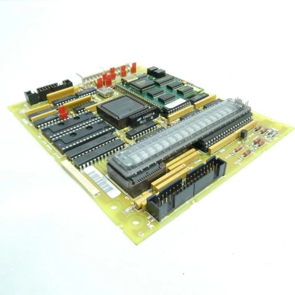
- Functional Acronym: TCEB (Turbine Control Exciter Board)
- Board Variant: G1 variant (specific hardware configuration)
- Revision: A (Board Revision A)
- Core Function: Exciter control processing and algorithm execution
- Control Algorithms: Exciter voltage regulation, reactive power control, exciter coordination
- Processor Type: Microprocessor-based exciter control processor
- Communication: Communication with exciter interface boards (TCEA) and Mark V processors
- Signal Processing: Digital and analog exciter signal processing capability
- Voltage Regulation: Voltage regulation control loop execution
- Reactive Power Control: VAR control and power factor regulation
- Memory: Program memory, data memory, configuration parameters for exciter algorithms
- Protection Features: Exciter protection monitoring and fault detection
- Diagnostic Features: Self-diagnostic capability and fault logging
- LED Indicators: Multiple LED indicators for status, communication, faults
- Power Requirements: Typically 24 V DC from control system power supply
- Dimensions: Standard Mark V board form factor (typically 3″ H × 11.5″ W)
- PCB Coating: Normal coating (non-conformal)
- Manual: GEH-6221 (Exciter Control Board Manual)

GE DS200SLCCG3ACC
The Real-World Problem It Solves
The Mark V control system in turbine-generator applications requires a dedicated exciter control processing board to execute exciter control algorithms, manage voltage regulation, and coordinate exciter operations with overall turbine control. The DS200TCEBG1A (Turbine Control Exciter Board – G1 Variant, Revision A) provides this critical exciter control processing capability, functioning as the exciter control processor that executes voltage regulation algorithms, reactive power control logic, and exciter coordination functions. While the TCEA board provides the interface between the Mark V system and exciter hardware, the TCEB board executes the control algorithms that determine exciter operation. This board receives setpoints and commands from Mark V control processors, processes exciter feedback signals through the TCEA interface, calculates appropriate exciter control outputs, and sends control commands to maintain generator voltage and reactive power at desired levels. Without this board, the Mark V system would lack the dedicated processing capability for exciter control algorithms, preventing precise voltage regulation and reactive power management.
Where you’ll typically find it:
- Exciter control racks in Mark V control cabinets
- Turbine-generator control systems requiring dedicated exciter control processing
- Power generation facilities with voltage regulation requirements
- Combined cycle plants with turbine-generator sets requiring VAR control
- Generator excitation control systems
- Applications requiring exciter control algorithm execution
Bottom line: Exciter control processing board—providing voltage regulation algorithms, reactive power control logic, and exciter coordination for precise generator excitation control.
Hardware Architecture & Under-the-Hood Logic
The DS200TCEBG1A (G1 Variant, Revision A) is the Turbine Control Exciter Board for the Mark V control system, serving as the exciter control processor that executes exciter control algorithms and manages exciter operations. Unlike the TCEA board which provides the interface to exciter hardware, the TCEB board executes the control algorithms that determine exciter behavior. The board contains a microprocessor that runs voltage regulation algorithms, reactive power control logic, and exciter coordination functions. The board receives setpoints and commands from Mark V control processors, receives exciter feedback signals through TCEA interface boards, calculates appropriate exciter control outputs based on algorithm execution, and sends control commands to maintain generator voltage and reactive power at desired levels. The board also includes protection monitoring and diagnostic capabilities to detect exciter faults, overvoltage conditions, underexcitation conditions, or other exciter-related issues, and communicates these conditions to the Mark V system for appropriate action.
Signal flow:
- Exciter setpoints and commands received from Mark V control processors
- Exciter feedback signals received through TCEA interface boards
- Feedback signals are processed and converted to digital values
- Microprocessor executes voltage regulation algorithms
- Reactive power control logic calculates required exciter output
- Exciter coordination logic coordinates exciter with turbine control
- Control outputs are calculated based on algorithm results
- Control commands are formatted for transmission to TCEA
- Control commands are sent to TCEA for exciter hardware control
- Protection monitoring circuits track exciter operating conditions
- Fault detection circuits identify exciter faults and abnormal conditions
- LED indicators display exciter control status, communication state, faults
- Diagnostic functions log exciter operational data and fault events
- Configuration parameters stored in non-volatile memory
- Power conditioning ensures stable operation from 24 V DC supply
GE DS200SLCCG3ACC
Field Service Pitfalls: What Rookies Get Wrong
Confusing TCEB with TCEA causes functional confusionMixing up TCEB and TCEA boards. I’ve seen technicians treating TCEB (control processor) as TCEA (interface board), causing exciter control system failures.
- Field Rule: Clearly distinguish TCEB vs. TCEA. TCEB is Turbine Control Exciter Board—executes exciter control algorithms. TCEA is Turbine Control Exciter Assembly Board—provides hardware interface. Check board label for “TCEB” designation. Never assume exciter boards are identical—TCEB is the processor, TCEA is the interface.
Skipping exciter algorithm parameter backup causes reconfiguration nightmareNot saving algorithm parameters before replacement. I’ve seen technicians replacing TCEB boards without backing up exciter algorithm parameters, requiring complete reconfiguration from scratch.
- Field Rule: Always backup exciter algorithm parameters before TCEB replacement. Document all voltage regulation setpoints, reactive power control parameters, exciter coordination settings, and tuning values. Use Mark V configuration tools to save parameter files. Photograph critical parameter screens. Never replace TCEB without backup—reconfiguring from scratch wastes hours and risks errors.
Forgetting to verify software compatibility causes algorithm execution failuresNot checking software version compatibility. I’ve seen technicians installing Revision A TCEB boards without verifying software compatibility, causing algorithm mismatches or execution failures.
- Field Rule: Verify software compatibility before installation. Revision A TCEB may require specific software version. Check that Mark V software supports Revision A features. Consult GEH-6221 manual for compatibility matrix. Never assume software is compatible—verify software requirements first.
Neglecting voltage regulation response testing causes instabilityNot testing voltage regulation after replacement. I’ve seen technicians installing TCEB boards without testing voltage regulation response, discovering instability during load changes or setpoint changes.
- Field Rule: Test voltage regulation response after TCEB installation. Verify voltage regulation responds correctly to setpoint changes. Test regulation response to load steps and reactive power changes. Verify regulation stability across operating range. Never assume voltage regulation works correctly—test regulation before placing in service.
Skipping reactive power control verification causes power factor issuesNot testing reactive power control. I’ve seen technicians installing TCEB boards without verifying reactive power control operation, causing power factor or VAR control issues.
- Field Rule: Test reactive power control after TCEB installation. Verify reactive power control responds correctly to commands. Test VAR control response to load changes. Verify power factor regulation meets requirements. Never assume reactive power control works correctly—test VAR control before placing in service.
Overlooking G1 variant characteristics causes compatibility issuesNot understanding G1-specific features. I’ve seen technicians treating G1 variant as generic TCEB, missing specialized capabilities or requirements.
- Field Rule: Learn G1 variant characteristics. G1 may support specific exciter control algorithms or communication protocols. G1 may have different processing capabilities or parameter ranges. Check system documentation for G1-specific requirements. Never assume G1 is generic TCEB—verify G1 specifications first.
Forgetting to test exciter coordination causes system conflictsNot verifying exciter-turbine coordination. I’ve seen technicians installing TCEB boards without testing exciter coordination with turbine control, causing system conflicts during operation.
- Field Rule: Test exciter coordination after TCEB installation. Verify exciter coordination with turbine startup sequences. Test exciter response to turbine load changes. Verify coordination during generator synchronization. Never assume exciter works in isolation—test coordination before placing in service.
Improper grounding causes exciter control noise and erratic operationIncorrect ground connections. I’ve seen technicians grounding TCEB incorrectly, introducing noise or ground loops into exciter control signals.
- Field Rule: Follow proper grounding procedures for exciter control boards. Use designated ground points from Mark V documentation. Avoid creating ground loops between exciter control and other grounds. Verify ground connections are secure and clean. Never improvise exciter control grounding—improper grounding causes erratic voltage regulation.
Skipping LED status interpretation causes missed exciter faultsMisreading LED indication patterns. I’ve seen technicians misunderstanding TCEB LED patterns, missing critical fault information about exciter control status or algorithm issues.
- Field Rule: Learn TCEB LED indication patterns. Understand what each LED indicates (processor status, algorithm execution, communication faults). Use LED information for fault diagnosis. Check documentation for G1-specific LED meanings. Never ignore LED indications—they provide early fault warning.
Assuming Revision A is compatible with Revision B without verification causes errorsReplacing Revision B with Revision A without verification. I’ve seen technicians downgrading from Revision B to Revision A without checking compatibility, causing feature loss or configuration errors.
- Field Rule: Verify Revision A compatibility before installation. Revision A may lack features present in Revision B. Check that configuration parameters are compatible. Update parameters if required for Revision A operation. Consult GEH-6221 manual for revision differences. Never assume revisions are interchangeable—verify compatibility first.
Commercial Availability & Pricing Note
Please note: The listed price is for reference only and is not binding. Final pricing and terms are subject to negotiation based on current market conditions and availability. As a specialized exciter control component, availability may be limited and lead times extended. TCEB boards require compatibility verification with specific exciter control algorithms and Mark V software versions.


