
Description
Hard-Numbers: Technical Specifications
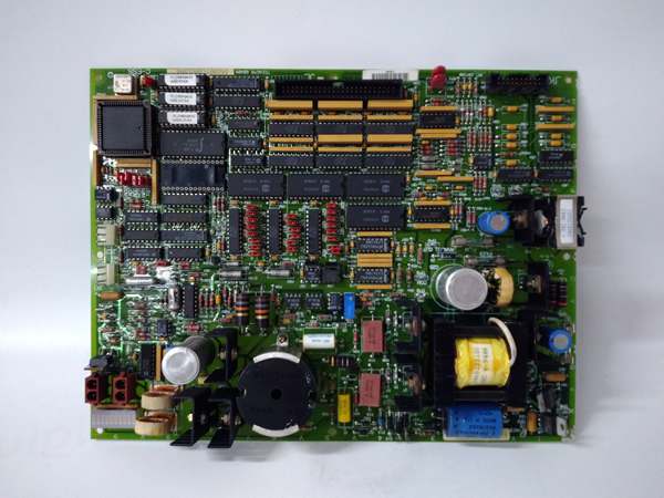
- Functional Acronym: TCEA (Turbine Control Exciter Assembly Board)
- Board Variant: G1 variant (specific hardware configuration)
- Revision: B (Board Revision B)
- Core Function: Exciter interface and control functionality
- Exciter Control: Exciter voltage regulation and control interfaces
- Communication: Enhanced communication with exciter controllers and Mark V processors
- Signal Types: Digital and analog exciter control signals
- Signal Conditioning: Enhanced conditioning for exciter feedback and control signals
- Voltage Regulation: Interface to voltage regulation control loops
- Generator Excitation: Support for generator excitation control functions
- Protection Features: Enhanced exciter protection monitoring and interface
- Diagnostic Features: Enhanced status indicators for exciter system monitoring
- LED Indicators: Multiple LED indicators for status, communication, faults
- Power Requirements: Typically 24 V DC from control system power supply
- Dimensions: Standard Mark V board form factor (typically 3″ H × 11.5″ W)
- PCB Coating: Normal coating (non-conformal)
- Manual: GEH-6220 (Exciter Interface Board Manual)

GE DS200TCEAG1B
The Real-World Problem It Solves
The Mark V control system in turbine-generator applications requires a specialized interface to communicate with and control turbine exciter systems for generator excitation and voltage regulation. The DS200TCEAG1B (Turbine Control Exciter Assembly Board – G1 Variant, Revision B) provides this critical exciter interface and control capability with enhancements over Revision A. Revision B incorporates improvements in communication protocols, signal conditioning accuracy, diagnostic capabilities, or exciter protection interfaces based on GE engineering change orders. The board serves as the communication bridge between the Mark V control system and exciter controllers, receiving exciter status and feedback signals, sending control commands for voltage regulation, and coordinating exciter operation with overall turbine control. The Revision B design may include enhanced features such as improved communication reliability, additional exciter parameter monitoring, expanded protection interface capabilities, or upgraded signal processing. These enhancements improve the reliability and accuracy of exciter control, providing better voltage regulation performance and more robust exciter protection. Without this board, the Mark V control system would lack the capability to communicate with and control the exciter, preventing integrated turbine-generator control and potentially leading to voltage instability or exciter protection trips.
Where you’ll typically find it:
- Exciter interface racks in Mark V control cabinets
- Turbine-generator control systems with integrated exciter control
- Power generation facilities requiring voltage regulation and exciter coordination
- Combined cycle plants with turbine-generator sets
- Generator excitation control systems
- Applications requiring enhanced exciter control and protection capabilities
Bottom line: Enhanced exciter interface and control board—providing improved communication, signal conditioning, and control interfaces between Mark V control system and turbine exciter for reliable generator excitation control.
Hardware Architecture & Under-the-Hood Logic
The DS200TCEAG1B (G1 Variant, Revision B) is the Turbine Control Exciter Assembly Board for the Mark V control system, serving as the primary interface between the Mark V control system and turbine exciter controllers with enhancements over Revision A. The Revision B design represents an evolution from the earlier revision, potentially incorporating improvements in communication protocols, signal conditioning accuracy, diagnostic capabilities, or exciter protection interfaces. The G1 variant design represents a specific hardware configuration optimized for particular exciter types or communication protocols. The board provides multiple interface functions: enhanced communication channels for exchanging data with exciter controllers, improved signal conditioning circuits for processing exciter feedback signals, and upgraded control output interfaces for sending exciter control commands. The board receives exciter status and feedback signals such as field voltage, field current, exciter operating status, protection relay status, and other exciter parameters. These signals are conditioned through enhanced filtering, isolation, and conversion circuits before being transmitted to Mark V control processors. The board also receives control commands from Mark V processors for exciter voltage regulation, reactive power control, and exciter operating mode changes. These commands are conditioned and transmitted to the exciter controller through enhanced communication interfaces. The board includes upgraded protection monitoring capabilities to detect exciter protection trips, overvoltage conditions, underexcitation conditions, or other exciter-related faults, and communicates these conditions to the Mark V system for appropriate action.
Signal flow:
- Exciter feedback signals from field devices enter TCEA through terminal connectors
- Enhanced input protection circuits limit voltage and current to protect board circuits
- Enhanced signal conditioning circuits filter and isolate exciter feedback signals
- Field voltage and current signals are converted to digital values via improved A/D converters
- Digital feedback values are formatted and transmitted to Mark V control processors
- Enhanced communication interfaces exchange data with exciter controllers
- Exciter status and protection signals are received and processed
- Control commands from Mark V processors are received through communication interfaces
- Control commands are conditioned and formatted for exciter controller communication
- Enhanced exciter control outputs are transmitted to exciter
- Enhanced protection monitoring circuits track exciter protection relay status
- Improved fault detection circuits identify exciter faults with enhanced accuracy
- Enhanced LED indicators display exciter status, communication state, and fault conditions
- Enhanced diagnostic functions detect communication failures or exciter interface issues
- Power conditioning ensures stable operation from 24 V DC supply
GE DS200TCEAG1B
Field Service Pitfalls: What Rookies Get Wrong
Assuming Revision B is drop-in compatible with Revision A causes configuration errorsInstalling Revision B without verifying configuration compatibility. I’ve seen technicians replacing Revision A TCEA with Revision B without checking configuration, causing parameter mismatches or communication failures.
- Field Rule: Verify Revision B configuration compatibility before installation. Check that configuration parameters are compatible between revisions. Update configuration parameters if required for Revision B. Consult GEH-6220 manual for revision changes. Never assume Revision B is drop-in compatible—verify configuration first.
Confusing TCEA with TCAA or other boards causes installation errorsMixing up TCEA and other interface boards. I’ve seen technicians installing TCAA (analog board) where TCEA (exciter board) belongs, causing exciter control failures.
- Field Rule: Clearly identify TCEA vs. other interface boards. TCEA is Turbine Control Exciter Assembly Board—exciter interface functions. TCAA is Terminal Card Analog Board—analog signal processing. Check board label for “TCEA” designation. Never assume interface boards are identical—TCEA handles exciter control.
Overlooking G1 variant characteristics causes compatibility issuesNot understanding G1-specific features. I’ve seen technicians treating G1 variant as generic TCEA, missing specialized capabilities or requirements.
- Field Rule: Understand G1 variant characteristics. G1 may support specific exciter types or communication protocols. G1 may have different interface configurations or signal types. Check system documentation for G1-specific requirements. Never assume G1 is generic TCEA—verify G1 specifications first.
Skipping Revision B-specific calibration causes accuracy issuesNot calibrating enhanced features. I’ve seen technicians using Revision A calibration procedures for Revision B boards, missing enhanced accuracy improvements.
- Field Rule: Use Revision B-specific calibration procedures. Revision B may have improved calibration ranges or procedures. Verify calibration accuracy with enhanced reference standards. Document calibration values using Revision B procedures. Never assume Revision A calibration works—use Revision B procedures.
Neglecting enhanced exciter communication verification causes coordination failuresNot testing enhanced communication links. I’ve seen technicians installing Revision B TCEA without verifying enhanced exciter communication features, causing communication issues.
- Field Rule: Verify enhanced exciter communication before placing in service. Test enhanced communication features with exciter controller. Verify enhanced data exchange is error-free. Check enhanced communication timeout settings. Never assume enhanced communication works—test features before turbine operation.
Forgetting to verify enhanced protection interface causes missed tripsNot properly interfacing enhanced protection signals. I’ve seen technicians misconnecting enhanced exciter protection relays, causing missed trips or nuisance trips.
- Field Rule: Properly interface enhanced exciter protection signals. Verify enhanced protection relay wiring to TCEA is correct. Check that enhanced protection trips are correctly communicated to Mark V. Test enhanced protection signal paths with simulated trips. Never assume enhanced protection wiring is correct—verify enhanced protection interfaces.
Overlooking Revision B diagnostic enhancements causes missed faultsNot utilizing enhanced diagnostic features. I’ve seen technicians installing Revision B boards but not understanding enhanced diagnostic capabilities, missing fault information.
- Field Rule: Learn Revision B diagnostic enhancements. Revision B may include additional diagnostic parameters or fault detection capabilities. Use enhanced diagnostic tools for fault identification. Document Revision B-specific diagnostic features. Never assume diagnostics are the same—utilize enhanced capabilities.
Improper grounding causes exciter noise and erratic operationIncorrect ground connections. I’ve seen technicians grounding TCEA incorrectly, introducing noise or ground loops into exciter control signals.
- Field Rule: Follow proper grounding procedures for exciter interfaces. Use designated ground points from Mark V and exciter documentation. Avoid creating ground loops between exciter and control grounds. Verify ground connections are secure and clean. Never improvise exciter grounding—improper grounding causes voltage regulation issues.
Skipping voltage regulation response testing causes instabilityNot testing voltage regulation response. I’ve seen technicians installing Revision B TCEA without testing voltage regulation response, discovering instability during load changes.
- Field Rule: Test voltage regulation response after Revision B installation. Verify voltage regulation responds correctly to setpoint changes. Test regulation response to load steps. Verify reactive power control operation. Never assume voltage regulation works correctly—test regulation before placing in service.
Forgetting to update software for Revision B causes communication failuresNot updating Mark V software for Revision B. I’ve seen technicians installing Revision B hardware without updating software, causing communication or compatibility issues.
- Field Rule: Update Mark V software for Revision B compatibility. Verify software version supports Revision B features. Update software if required for Revision B operation. Test software-hardware compatibility after update. Never assume software is compatible—update if required.
Commercial Availability & Pricing Note
Please note: The listed price is for reference only and is not binding. Final pricing and terms are subject to negotiation based on current market conditions and availability. As a specialized exciter interface component with enhanced features, availability may be limited and lead times extended. Revision B boards may command premium pricing due to enhanced capabilities.


