
Description
Hard-Numbers: Technical Specifications
- Functional Acronym: TCEA (Turbine Control Exciter Assembly Board)
- Board Variant: G1 variant (specific hardware configuration)
- Revision: A (Board Revision A)
- Core Function: Exciter interface and control functionality
- Exciter Control: Exciter voltage regulation and control interfaces
- Communication: Communication with exciter controllers and Mark V processors
- Signal Types: Digital and analog exciter control signals
- Signal Conditioning: Conditioning for exciter feedback and control signals
- Voltage Regulation: Interface to voltage regulation control loops
- Generator Excitation: Support for generator excitation control functions
- Protection Features: Exciter protection monitoring and interface
- Diagnostic Features: Status indicators for exciter system monitoring
- LED Indicators: Multiple LED indicators for status, communication, faults
- Power Requirements: Typically 24 V DC from control system power supply
- Dimensions: Standard Mark V board form factor (typically 3″ H × 11.5″ W)
- PCB Coating: Normal coating (non-conformal)
- Manual: GEH-6220 (Exciter Interface Board Manual)

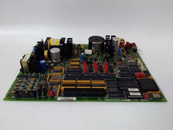
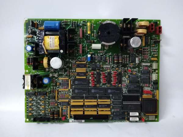
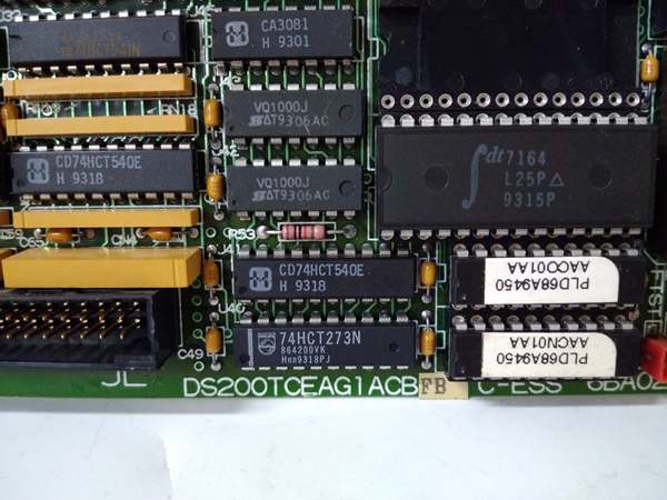
GE DS200TCEAG1A
The Real-World Problem It Solves
The Mark V control system in turbine-generator applications requires a specialized interface to communicate with and control turbine exciter systems for generator excitation and voltage regulation. The DS200TCEAG1A (Turbine Control Exciter Assembly Board – G1 Variant, Revision A) provides this critical exciter interface and control capability, serving as the communication bridge between the Mark V control system and exciter controllers. Turbine exciters are essential components that generate and regulate the DC field current for the generator rotor, controlling generator output voltage and reactive power. The exciter must be precisely controlled to maintain stable generator voltage, support reactive power requirements, and respond to system load changes. The TCEA board interfaces with the exciter controller, receiving exciter status and feedback signals, sending control commands for voltage regulation, and coordinating exciter operation with overall turbine control. This board also provides signal conditioning for exciter-related signals, ensuring accurate measurement of exciter parameters such as field voltage, field current, and exciter status. Without this board, the Mark V control system would lack the capability to communicate with and control the exciter, preventing integrated turbine-generator control and potentially leading to voltage instability or exciter protection trips.
Where you’ll typically find it:
- Exciter interface racks in Mark V control cabinets
- Turbine-generator control systems with integrated exciter control
- Power generation facilities requiring voltage regulation and exciter coordination
- Combined cycle plants with turbine-generator sets
- Generator excitation control systems
- Applications requiring Mark V to exciter communication and control
Bottom line: Exciter interface and control board—providing communication, signal conditioning, and control interfaces between Mark V control system and turbine exciter for integrated generator excitation control.
Hardware Architecture & Under-the-Hood Logic
The DS200TCEAG1A (G1 Variant, Revision A) is the Turbine Control Exciter Assembly Board for the Mark V control system, serving as the primary interface between the Mark V control system and turbine exciter controllers. The G1 variant design represents a specific hardware configuration optimized for particular exciter types or communication protocols. The board provides multiple interface functions: communication channels for exchanging data with exciter controllers, signal conditioning circuits for processing exciter feedback signals, and control output interfaces for sending exciter control commands. The board receives exciter status and feedback signals such as field voltage, field current, exciter operating status, protection relay status, and other exciter parameters. These signals are conditioned through filtering, isolation, and conversion circuits before being transmitted to Mark V control processors for processing and monitoring. The board also receives control commands from Mark V processors for exciter voltage regulation, reactive power control, and exciter operating mode changes. These commands are conditioned and transmitted to the exciter controller through appropriate communication interfaces. The board includes protection monitoring capabilities to detect exciter protection trips, overvoltage conditions, underexcitation conditions, or other exciter-related faults, and communicates these conditions to the Mark V system for appropriate action.
Signal flow:
- Exciter feedback signals from field devices enter TCEA through terminal connectors
- Input protection circuits limit voltage and current to protect board circuits
- Signal conditioning circuits filter and isolate exciter feedback signals
- Field voltage and current signals are converted to digital values via A/D converters
- Digital feedback values are formatted and transmitted to Mark V control processors
- Communication interfaces exchange data with exciter controllers
- Exciter status and protection signals are received and processed
- Control commands from Mark V processors are received through communication interfaces
- Control commands are conditioned and formatted for exciter controller communication
- Exciter control outputs (voltage regulation, mode changes) are transmitted to exciter
- Protection monitoring circuits track exciter protection relay status
- Fault detection circuits identify exciter overvoltage, underexcitation, or other faults
- LED indicators display exciter status, communication state, and fault conditions
- Diagnostic functions detect communication failures or exciter interface issues
- Power conditioning ensures stable operation from 24 V DC supply
GE DS200TCEAG1A
Field Service Pitfalls: What Rookies Get Wrong
Confusing TCEA with TCAA or other boards causes installation errorsMixing up TCEA and other interface boards. I’ve seen technicians installing TCAA (analog board) where TCEA (exciter board) belongs, causing exciter control failures.
- Field Rule: Clearly identify TCEA vs. other interface boards. TCEA is Turbine Control Exciter Assembly Board—exciter interface functions. TCAA is Terminal Card Analog Board—analog signal processing. Check board label for “TCEA” designation. Never assume interface boards are identical—TCEA handles exciter control.
Overlooking G1 variant characteristics causes compatibility issuesNot understanding G1-specific features. I’ve seen technicians treating G1 variant as generic TCEA, missing specialized capabilities or requirements.
- Field Rule: Understand G1 variant characteristics. G1 may support specific exciter types or communication protocols. G1 may have different interface configurations or signal types. Check system documentation for G1-specific requirements. Never assume G1 is generic TCEA—verify G1 specifications first.
Skipping exciter communication verification causes coordination failuresNot testing communication links. I’ve seen technicians installing TCEA boards without verifying exciter communication, causing control coordination issues during startup.
- Field Rule: Verify exciter communication before placing in service. Test communication links with exciter controller. Verify data exchange is bidirectional and error-free. Check communication timeout settings. Never assume communication works—test links before turbine operation.
Neglecting exciter protection interface causes missed tripsNot properly interfacing protection signals. I’ve seen technicians misconnecting exciter protection relays, causing missed trips or nuisance trips.
- Field Rule: Properly interface exciter protection signals. Verify protection relay wiring to TCEA is correct. Check that protection trips are correctly communicated to Mark V. Test protection signal paths with simulated trips. Never assume protection wiring is correct—verify protection interfaces.
Forgetting to verify exciter feedback accuracy causes control errorsNot calibrating feedback signals. I’ve seen technicians installing TCEA boards without calibrating exciter feedback, causing voltage regulation errors.
- Field Rule: Calibrate exciter feedback signals after installation. Verify field voltage and current readings match actual values. Use known references to validate accuracy. Document calibration values. Never assume feedback is accurate—calibrate after replacement.
Improper grounding causes exciter noise and erratic operationIncorrect ground connections. I’ve seen technicians grounding TCEA incorrectly, introducing noise or ground loops into exciter control signals.
- Field Rule: Follow proper grounding procedures for exciter interfaces. Use designated ground points from Mark V and exciter documentation. Avoid creating ground loops between exciter and control grounds. Verify ground connections are secure and clean. Never improvise exciter grounding—improper grounding causes voltage regulation issues.
Skipping exciter mode verification causes operational issuesNot confirming exciter operating modes. I’ve seen technicians installing TCEA boards without verifying exciter mode configuration, causing mode mismatches during operation.
- Field Rule: Verify exciter mode configuration after installation. Confirm exciter operating modes match system requirements. Check mode switch settings and parameters. Test mode transitions. Never assume exciter modes are correct—verify modes before placing in service.
Overlooking LED status interpretation causes missed exciter faultsMisreading LED indication patterns. I’ve seen technicians misunderstanding TCEA LED patterns, missing critical fault information about exciter status or communication issues.
- Field Rule: Learn TCEA LED indication patterns. Understand what each LED indicates (exciter status, communication state, protection faults). Use LED information for fault diagnosis. Check documentation for G1-specific LED meanings. Never ignore LED indications—they provide early fault warning.
Forgetting to check voltage regulation response causes instabilityNot testing voltage regulation. I’ve seen technicians installing TCEA boards without testing voltage regulation response, discovering instability during load changes.
- Field Rule: Test voltage regulation response after installation. Verify voltage regulation responds correctly to setpoint changes. Test regulation response to load steps. Verify reactive power control operation. Never assume voltage regulation works correctly—test regulation before placing in service.
Confusing exciter control types causes installation errorsApplying wrong exciter control configuration. I’ve seen technicians configuring TCEA for wrong exciter type, causing control incompatibility.
- Field Rule: Verify exciter type before configuration. Identify exciter type (static, brushless, rotating). Confirm TCEA configuration matches exciter type. Check parameter settings for exciter-specific requirements. Never assume configuration is correct—verify exciter type compatibility first.
Commercial Availability & Pricing Note
Please note: The listed price is for reference only and is not binding. Final pricing and terms are subject to negotiation based on current market conditions and availability. As a specialized exciter interface component, availability may be limited and lead times extended. TCEA boards may require compatibility verification with specific exciter types and configurations.


