
Description
Hard-Numbers: Technical Specifications
- Functional Acronym: TCDA (Terminal Card Interface Board)
- Board Variant: DB revision (specific hardware revision)
- Group Number: G1 (Group 1 variant)
- Revision: B (Board Revision B)
- Core Function: Signal conditioning and terminal board interface
- Input/Output: Digital and analog signal processing capability
- Isolation: Electrical isolation between field devices and control processors
- Signal Types: Supports discrete signals, analog signals, feedback signals
- Terminal Board Interface: Interface to multiple terminal board types
- Communication: Communication with Mark V control processors and other boards
- Diagnostic Features: Status indicators for signal and communication monitoring
- LED Indicators: Multiple LED indicators for status, communication, faults
- Power Requirements: Typically 24 V DC from control system power supply
- Dimensions: Standard Mark V board form factor (typically 3″ H × 11.5″ W)
- PCB Coating: Normal coating (non-conformal)
- Manual: GEH-6215 (Terminal Interface Board Manual)

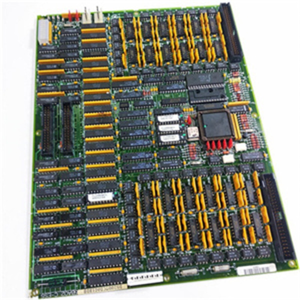
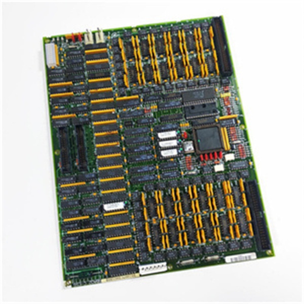
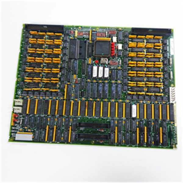
GE DS200TCDAG1BDB
The Real-World Problem It Solves
The Mark V control system requires reliable signal conditioning and isolation between field devices and control processors to ensure accurate signal transmission and protect sensitive control electronics from field transients and noise. The DS200TCDAG1BDB (Terminal Card Interface Board – Group 1, DB Revision) provides this critical interface function, conditioning signals from terminal boards, providing electrical isolation, and ensuring clean signal transmission to control processors. Field devices connected through terminal boards generate various signal types—discrete inputs, analog signals, feedback signals—that require conditioning before being processed by the control system. The TCDA board filters, isolates, and conditions these signals, protecting control processors from electrical noise, ground loops, and voltage spikes that could cause erratic operation or damage. Without this board, signals from terminal boards would be susceptible to noise and interference, leading to inaccurate readings, control instability, or potential damage to control processors.
Where you’ll typically find it:
- Interface racks between terminal boards and control processors
- Signal conditioning assemblies in Mark V control cabinets
- Isolation barriers between field devices and control electronics
- Analog signal conditioning modules
- Digital signal interface assemblies
- Terminal board interface applications requiring signal conditioning
Bottom line: Signal conditioning and interface board—providing electrical isolation and signal processing between terminal boards and control processors for reliable operation.
Hardware Architecture & Under-the-Hood Logic
The DS200TCDAG1BDB (Group 1, DB Revision) is the Terminal Card Interface Board for the Mark V control system, serving as the signal conditioning and interface bridge between terminal boards and control processors. The DB revision design represents a specific hardware configuration optimized for particular terminal board types or signal requirements. The board provides multiple functions: signal conditioning to clean and normalize signals from terminal boards, electrical isolation to protect control processors from field transients, and interface logic to enable communication between terminal boards and control processors. The board receives signals from terminal boards through interface connectors, processes these signals through conditioning circuits that may include filtering, amplification, or conversion functions, and routes conditioned signals to control processors through appropriate interfaces. The isolation circuitry ensures that electrical disturbances from field devices do not propagate to control processors, protecting sensitive electronics. The board also includes status monitoring and diagnostic capabilities to detect signal faults, communication failures, or board malfunctions.
Signal flow:
- Signals from field devices route through terminal boards to TCDA
- Input signals enter TCDA through interface connectors
- Signal conditioning circuits filter and normalize input signals
- Isolation circuitry provides electrical separation between field and control circuits
- Analog signals are amplified or converted to standard ranges
- Digital signals are debounced and conditioned for logic processing
- Feedback signals are processed and conditioned for control loop feedback
- Conditioned signals are routed to control processors through output interfaces
- Communication circuits enable data exchange with control processors
- Status monitoring circuits track signal integrity and board health
- LED indicators display signal status, communication state, fault conditions
- Diagnostic functions detect signal faults, isolation failures, or board malfunctions
- Power conditioning ensures stable operation from 24 V DC supply
- Ground isolation prevents ground loops and noise propagation
- Output signals provide clean, reliable data to control processors
GE DS200TCDAG1BDB
Field Service Pitfalls: What Rookies Get Wrong
Confusing TCDA with TCAA or other terminal boards causes installation errorsMixing up TCDA and other interface boards. I’ve seen technicians installing TCDA where TCAA or other boards belong, causing communication failures or signal issues.
- Field Rule: Clearly identify TCDA vs. other terminal interface boards. TCDA is Terminal Card Interface Board—provides signal conditioning and isolation. TCAA is Terminal Card Analog Board—different functionality. Check board label for “TCDA” designation. Never assume terminal interface boards are identical—each serves specific functions.
Overlooking DB revision characteristics causes compatibility issuesNot understanding DB-specific features. I’ve seen technicians treating DB revision as standard TCDA, missing specialized capabilities or requirements.
- Field Rule: Understand DB revision characteristics. DB revision may support specific terminal board types or signal configurations. DB may have different connector pinouts or signal conditioning capabilities. Check system documentation for DB-specific requirements. Never assume DB is standard TCDA—verify DB revision specifications first.
Forgetting to verify isolation integrity causes damage to control processorsNot checking isolation circuits. I’ve seen technicians installing TCDA boards without verifying isolation integrity, allowing field transients to damage control processors.
- Field Rule: Verify isolation integrity before and after installation. Use insulation resistance tester to check isolation between field and control circuits. Verify ground isolation is intact. Check that isolation barriers are functional. Never install TCDA without verifying isolation—damaged control processors cost thousands.
Skipping signal continuity checks causes input/output failuresNot testing signal paths. I’ve seen technicians installing TCDA boards without verifying signal continuity, discovering breaks or miswiring during system startup.
- Field Rule: Perform signal continuity checks during installation. Verify each signal path from terminal board through TCDA to control processor. Check for opens, shorts, or misconnections. Use multimeter to verify signal integrity. Never assume signal paths are correct—verify continuity before energizing.
Improper grounding causes noise and erratic operationIncorrect ground connections. I’ve seen technicians grounding TCDA incorrectly, introducing noise or ground loops into signal paths.
- Field Rule: Follow proper grounding procedures. Use designated ground points from Mark V documentation. Avoid creating ground loops between field and control grounds. Verify ground connections are secure and clean. Never improvise grounding schemes—improper grounding causes unpredictable operation.
Neglecting LED status interpretation causes missed faultsMisreading LED indication patterns. I’ve seen technicians misunderstanding TCDA LED patterns, missing critical fault information about signal or communication issues.
- Field Rule: Learn TCDA LED indication patterns. Understand what each LED indicates (signal status, communication state, isolation faults). Use LED information for fault diagnosis. Check documentation for DB-specific LED meanings. Never ignore LED indications—they provide early fault warning.
Assuming TCDA is compatible with all terminal boards causes failuresConnecting incompatible terminal boards. I’ve seen technicians connecting unsupported terminal board types to TCDA, causing signal compatibility issues.
- Field Rule: Verify terminal board compatibility. Check that terminal board types are supported by TCDA configuration. Confirm signal types and levels are compatible. Consult system documentation for compatibility matrix. Never assume all terminal boards work with TCDA—verify compatibility first.
Forgetting to check power supply quality causes intermittent operationNot verifying clean power. I’ve seen technicians installing TCDA boards without checking power quality, causing erratic signal conditioning or board malfunctions.
- Field Rule: Verify power supply quality before and after installation. Measure 24 V DC supply for ripple and noise. Check voltage stability during signal load changes. Ensure proper grounding of power supply. Never install TCDA with unstable power—noise causes erratic behavior.
Skipping signal calibration after replacement causes inaccurate readingsNot calibrating signal conditioning circuits. I’ve seen technicians replacing TCDA boards without calibrating signal conditioning, causing inaccurate readings or control errors.
- Field Rule: Calibrate signal conditioning circuits after replacement. Use Mark V calibration procedures for analog signals. Verify signal accuracy with known references. Document calibration values. Never assume signal conditioning is accurate—calibrate after replacement.
Commercial Availability & Pricing Note
Please note: The listed price is for reference only and is not binding. Final pricing and terms are subject to negotiation based on current market conditions and availability. As a specialized interface component, availability may be limited and lead times extended.


