
Description
Hard-Numbers: Technical Specifications
- Functional Acronym: TCCA (Turbine Control Card Assembly)
- Group Number: G8 (Group 8 variant)
- Revision: B (Board Revision B)
- Core Location: Control Core (R> processor rack) – Location 1, 2, or 3 (varies by Group 8 configuration)
- Processor Type: Microprocessor-based governor control processor
- Control Algorithms: Speed control, load control, governor algorithms, sequencer logic
- Memory: Program memory, data memory, configuration parameters
- Communication Interface: Communication with other Mark V boards and HMIs
- I/O Processing: Digital input/output processing, analog input/output processing
- Redundancy: Part of redundant R> processor architecture
- Operator Interface: HMI communication capability
- Diagnostic Features: Self-diagnostic capability, fault logging
- LED Indicators: Multiple LED indicators for status, faults, communication
- Power Requirements: Typically 24 V DC from control system power supply
- Dimensions: Standard Mark V board form factor (typically 3″ H × 11.5″ W)
- PCB Coating: Normal coating (non-conformal)
- Manual: GEH-6218 (Turbine Control Card Assembly Manual)

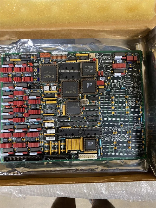
GE DS200TCCBG8B
The Real-World Problem It Solves
The Mark V control system requires a central governor control processing board that executes speed/load control algorithms, maintains turbine speed within tight tolerances, and coordinates all turbine operational sequences. The DS200TCCBG8B (Turbine Control Card Assembly – Group 8, Revision B) provides this core control processing capability for applications requiring the specialized capabilities of the Group 8 configuration. The Group 8 variant is engineered to support specific control scenarios or turbine applications that differ from other group configurations—this may include unique algorithm sets, enhanced processing capabilities, specialized I/O requirements, or application-specific governor logic. The revision B design incorporates improvements over earlier revisions, potentially enhancing algorithm accuracy, processing performance, or diagnostic capabilities. The board processes inputs from speed sensors, pressure transmitters, temperature sensors, and other field devices, then generates control outputs to fuel valves, steam valves, and other actuators to maintain desired turbine operation. Without this Group 8 TCCA board, Mark V systems requiring the Group 8 control architecture would lack the necessary processing capability, leading to control limitations or inability to meet application-specific requirements.
Where you’ll typically find it:
- Control Core (R> processor rack) – Location varies by Group 8 system configuration
- Gas turbine control systems requiring Group 8 governor control capabilities
- Steam turbine control systems with Group 8 control architecture
- Applications requiring specialized control algorithms or I/O configurations
- Systems with redundant R> processor architecture requiring Group 8 controllers
- Turbines with specific control requirements addressed by Group 8 variant
Bottom line: Group 8 governor control processing board—revision B configuration, implementing specialized speed/load control algorithms and turbine coordination for applications requiring Group 8 capabilities.
Hardware Architecture & Under-the-Hood Logic
The DS200TCCBG8B (Group 8, Revision B) is the Turbine Control Card Assembly for the Mark V control system, serving as the governor control processing board for applications requiring the Group 8 configuration. The Group 8 variant is specifically designed to address particular control scenarios or turbine applications that differentiate it from other TCCA groups—this may include specialized control algorithms, unique I/O processing capabilities, enhanced performance characteristics, or application-specific governor logic implementation. The revision B design represents an evolution from earlier Group 8 revisions, potentially incorporating improvements in processor performance, algorithm sophistication, diagnostic capabilities, or hardware reliability. The board executes speed/load control algorithms, governor logic, and turbine coordination functions. Inputs from speed sensors, pressure transmitters, temperature sensors, and other field devices are processed through the board’s input conditioning circuits and converted to digital values for the governor algorithms. Control outputs are generated and routed through output conditioning circuits to drive fuel valves, steam valves, and other actuators. The board communicates with other Mark V boards, HMIs, and external systems for coordinated turbine operation.
Signal flow:
- Field device inputs (speed, pressure, temperature, status) route through terminal boards to TCCA
- Input conditioning circuitry filters and prepares signals for processing
- Analog-to-digital converters convert analog signals to digital values
- Governor algorithms (speed control, load control) execute on microprocessor
- Sequencer logic coordinates turbine startup, operation, and shutdown sequences
- Control outputs generated based on algorithm results and setpoints
- Output conditioning circuitry prepares control signals for actuation
- Control outputs route through interface boards to fuel valves, steam valves, actuators
- Communication with other Mark V boards (SIOB, SDCC, terminal boards)
- HMI communication provides operator interface and monitoring
- Self-diagnostic routines monitor board health and fault conditions
- Fault logging captures diagnostic information for troubleshooting
- LED indicators display status, faults, communication states
- Redundant R> processor architecture ensures reliability
- Group 8 may include specialized algorithm sets or I/O configurations
GE DS200TCCBG8B
Field Service Pitfalls: What Rookies Get Wrong
Assuming Group 8 is interchangeable with other groups causes installation failuresTreating all TCCA groups as equivalent. I’ve seen technicians replacing Group 8 TCCA with Group 1 or other group boards, causing control failures or algorithm mismatches.
- Field Rule: Understand Group 8-specific characteristics. Group 8 has unique control capabilities or algorithm sets that differ from other groups. Application may require specific Group 8 features. Check system documentation for Group 8 requirements. Never assume groups are interchangeable—Group 8 serves specific control scenarios.
Confusing Group 8 with Group 1 TCCA causes control instabilityMixing up Group 8 and Group 1 boards. I’ve seen technicians installing Group 1 TCCA where Group 8 belongs, leading to incorrect control behavior or missing capabilities.
- Field Rule: Clearly identify Group 8 vs. Group 1. Group 8 may have different algorithm implementations or I/O configurations. Group 8 may support specialized turbine applications that Group 1 does not. Check board label for “G8” designation. Never assume Group 1 works in Group 8 applications—verify group requirements first.
Forgetting to backup configuration parameters causes reconfiguration nightmareNot saving configuration before replacement. I’ve seen technicians replacing Group 8 TCCA boards without backing up parameters, forcing complete reconfiguration from scratch.
- Field Rule: Always backup configuration parameters before Group 8 TCCA replacement. Document all governor setpoints, sequencer steps, calibration values, and operational parameters. Use Mark V configuration tools to save parameter files. Photograph critical parameter screens. Never replace TCCA without backup—reconfiguring from scratch wastes hours and risks errors.
Skipping revision B compatibility verification causes installation failuresInstalling revision B without checking compatibility. I’ve seen technicians replacing earlier Group 8 TCCA revisions with revision B boards without verifying compatibility, leading to configuration errors or processing failures.
- Field Rule: Verify revision B compatibility before installation. Revision B may require different software version or parameter formats. Check R> processor software version compatibility. Verify control algorithms in software match revision B capabilities. Consult GEH-6218 manual for revision compatibility requirements. Never assume revision B is drop-in compatible—verify compatibility first.
Overlooking Group 8-specific algorithms causes control response issuesNot understanding Group 8 algorithm characteristics. I’ve seen technicians expecting Group 8 to behave like other groups, causing unexpected control responses or operational issues.
- Field Rule: Learn Group 8-specific algorithm characteristics. Group 8 may use different PID parameters or control logic than other groups. Control response characteristics may differ from Group 1 or other configurations. Check Group 8-specific tuning procedures and parameters. Never assume Group 8 algorithms match other groups—learn Group 8 requirements.
Neglecting redundancy coordination causes controller conflictsNot synchronizing redundant controllers. I’ve seen technicians replacing Group 8 TCCA boards in redundant systems without coordinating with other R> processors, causing controller conflicts.
- Field Rule: Coordinate with redundant controllers during replacement. Verify redundant controller states before replacement. Follow proper controller takeover/standby procedures. Re-synchronize controllers after replacement. Test redundancy switchover function. Never replace TCCA in redundant system without considering other controllers—redundancy requires coordination.
Forgetting to test control algorithms after replacement causes latent faultsNot verifying governor operation. I’ve seen technicians installing Group 8 TCCA boards but not testing speed/load control, discovering issues only during turbine startup.
- Field Rule: Always test governor control algorithms after Group 8 TCCA installation. Verify speed control response with simulated speed changes. Test load control operation with simulated load changes. Verify sequencer logic executes correctly. Check all control outputs respond appropriately to commands. Use Mark V diagnostic tools to confirm algorithm execution. Never assume control algorithms work correctly—verify governor operation before placing in service.
Misinterpreting revision B LED patterns causes missed faultsReading LED patterns with outdated references. I’ve seen technicians using revision A LED guides for revision B boards, misdiagnosing fault conditions.
- Field Rule: Learn revision B LED indication patterns. Revision B may have different LED flash patterns or additional indicators. Understand what each LED indicates (processor status, communication state, fault type). Use LED information for fault diagnosis. Never assume LED patterns match earlier revisions—learn revision B-specific patterns.
Improper parameter transfer causes Group 8 instabilityIncorrectly transferring parameters to new board. I’ve seen technicians using parameters from different turbine models or configurations, causing unstable operation.
- Field Rule: Transfer parameters carefully using compatible tools. Use Mark V parameter transfer utilities, not manual entry. Verify all critical parameters match original Group 8 configuration. Check that algorithm settings correspond to Group 8 characteristics. Never use parameters from different group configurations—each group has unique requirements.
Commercial Availability & Pricing Note
Please note: The listed price is for reference only and is not binding. Final pricing and terms are subject to negotiation based on current market conditions and availability. As a specialized Group 8 control component, availability may be limited and lead times extended.


