
Description
Key Technical Specifications
-
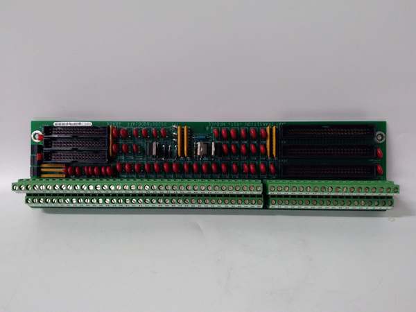
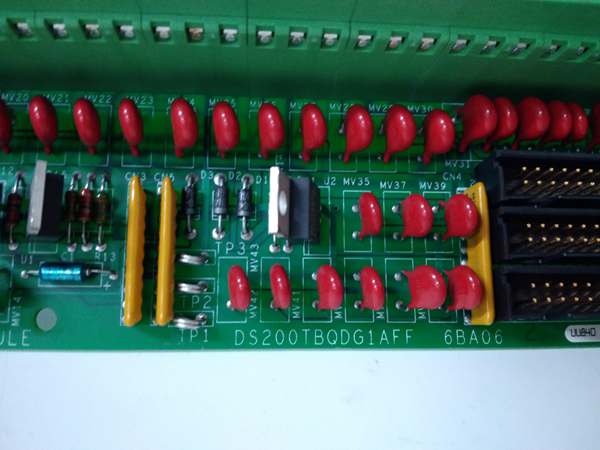
Model Number: DS200TBQDG1AFF
-
Manufacturer: General Electric (GE)
-
Channels: 8 analog inputs / outputs, ±10 V range
-
Accuracy: 0.1 % full-scale
-
Isolation: 2500 Vrms channel-to-ground
-
Communication: RS-485 on-board
-
Power Supply: 24 VDC (18-36 V)
-
Operating Temperature: –40 °C…+70 °C
-
Termination: 2 × 10⁷-point screw blocks (214 total)
-
Connectors: 3 × 34-pin header, J1/J2/J3
-
Test Points: 3 (TP1, TP2, TP3) for signal injection / verification
-
Jumpers: 2 berg jumpers for range / filter selection
-
Dimensions: 203 × 61 × 25 mm, 0.25 kg
-
Protection: IP20 (rack) / IP65 front option

GE DS200TBQDG1AFF
Field Application & Problem Solved
In the field the biggest pain is landing dozens of analog cables—LVDTs on the governor valve, milliamp loops from the pressure transmitters, and ±10 V signals from the servo amps—without turning the turbine cabinet into a spaghetti bowl. The DS200TBQDG1AFF solves that by giving you eight isolated ±10 V channels on one plug-in card. Slide it into the Mark VI rack, land the wires on the two 107-point screw blocks, and you’re done. You’ll typically find this board on 7EA or 9F peakers where every servo and transmitter in the skid has to report back to the Speedtronic. Core value: it collapses three DIN-rail terminal strips, 2500 V isolators, and pull-down resistors into a 6-inch card you can swap with the turbine on turning gear—no re-calibration, no external hardware.
In the field the biggest pain is landing dozens of analog cables—LVDTs on the governor valve, milliamp loops from the pressure transmitters, and ±10 V signals from the servo amps—without turning the turbine cabinet into a spaghetti bowl. The DS200TBQDG1AFF solves that by giving you eight isolated ±10 V channels on one plug-in card. Slide it into the Mark VI rack, land the wires on the two 107-point screw blocks, and you’re done. You’ll typically find this board on 7EA or 9F peakers where every servo and transmitter in the skid has to report back to the Speedtronic. Core value: it collapses three DIN-rail terminal strips, 2500 V isolators, and pull-down resistors into a 6-inch card you can swap with the turbine on turning gear—no re-calibration, no external hardware.
Installation & Maintenance Pitfalls (Expert Tips)
Jumper Side Wrong = Wrong Range
The silk-screen is read from the component side; flip the card and the berg jumpers land on the wrong pads. Result: ±10 V inputs become ±5 V, the DSP sees half-scale, and you chase a “servo offset” that isn’t there. Match the jumper map in GEI-100161 before you torque the screws.
The silk-screen is read from the component side; flip the card and the berg jumpers land on the wrong pads. Result: ±10 V inputs become ±5 V, the DSP sees half-scale, and you chase a “servo offset” that isn’t there. Match the jumper map in GEI-100161 before you torque the screws.
Terminal Torque 0.8 Nm – No More
Over-tighten and the screw posts crack; under-tighten and vibration walks the wire out. Use a calibrated screwdriver and stop when the washer flattens—then tug-test every wire.
Over-tighten and the screw posts crack; under-tighten and vibration walks the wire out. Use a calibrated screwdriver and stop when the washer flattens—then tug-test every wire.
IP20 Means Keep the Door Closed
The front is open; wash-down or salt mist will corrode the screw posts and give you intermittent “signal bounce.” If the cabinet fan ingests salt, bag the card during maintenance or mount it behind a filtered door.
The front is open; wash-down or salt mist will corrode the screw posts and give you intermittent “signal bounce.” If the cabinet fan ingests salt, bag the card during maintenance or mount it behind a filtered door.
Wire Dress – Flat or the Door Won’t Close
214 wires in a 6-inch slot is tight; leave the harness proud and the cabinet door pinches a conductor against the sheet-metal—ground fault that trips the whole Mark VI. Lace the bundle flat and strap it to the card stand-offs.
214 wires in a 6-inch slot is tight; leave the harness proud and the cabinet door pinches a conductor against the sheet-metal—ground fault that trips the whole Mark VI. Lace the bundle flat and strap it to the card stand-offs.
GE DS200TBQDG1AFF
Technical Deep Dive & Overview
Internally the card is a passive termination array—no CPU, no firmware. Each channel hits a 0.1 % precision divider, a 1 ms RC filter, and a 2500 V opto-isolator that feeds the DSP a clean ±10 V differential signal. Because it’s pure hardware you can hot-swap it: pull the old card, land the wires exactly where they came from, snap the 34-pin connectors in, and the turbine sees all analogs again in under five minutes.
Internally the card is a passive termination array—no CPU, no firmware. Each channel hits a 0.1 % precision divider, a 1 ms RC filter, and a 2500 V opto-isolator that feeds the DSP a clean ±10 V differential signal. Because it’s pure hardware you can hot-swap it: pull the old card, land the wires exactly where they came from, snap the 34-pin connectors in, and the turbine sees all analogs again in under five minutes.


