
Description
Hard-Numbers: Technical Specifications
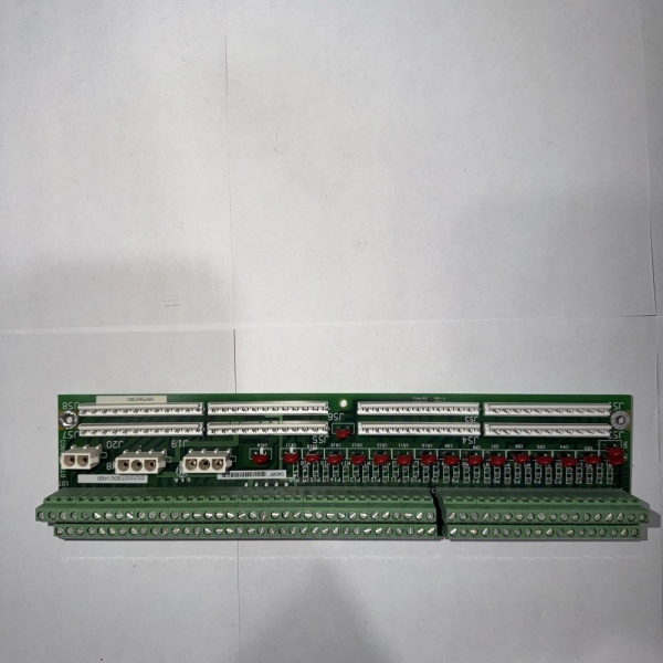
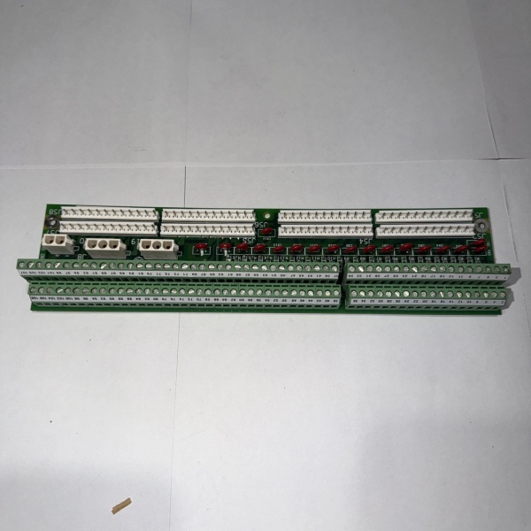
- Functional Acronym: TBQA (Terminal Board Quadrature Analog)
- Group Number: G1 (Group 1 variant)
- Revision: BA (Board Revision B, Artwork Revision A)
- Core Location: Control Core (R> processor rack) – varies by system configuration
- Terminal Blocks: Multiple terminal blocks for quadrature encoder wiring
- Encoder Channels: Support for A, B, and Z (index) quadrature channels
- Signal Types: Differential quadrature signals (A+, A-, B+, B-, Z+)
- Signal Conditioning: Differential receiver circuitry for noise immunity
- Encoder Power: Provides power to quadrature encoders (typically +5V or +12V)
- Direction Detection: Automatic shaft rotation direction detection
- Speed Output: Processed speed signals to R> governor control
- Position Output: High-resolution position data output
- LED Indicators: LED indicators for power status, signal presence, and fault conditions
- Power Requirements: Typically 24 V DC from control system power supply
- Dimensions: Standard Mark V board form factor (typically 3″ H × 11.5″ W)
- PCB Coating: Normal coating (non-conformal)
- Manual: GEH-6215 (Quadrature Terminal Board Manual)
The Real-World Problem It Solves
The Mark V control system requires a dedicated termination point for quadrature encoders that provide high-resolution shaft speed and position feedback for precise governor control. Unlike magnetic pickup sensors that only provide frequency-based speed signals, quadrature encoders deliver both speed and precise position data with directional information. The DS200TBQAG1ABA (Quadrature Terminal Board – Group 1, Revision BA) provides this termination and signal conditioning capability, offering differential receiver circuits for noise immunity, encoder power supply, and processed speed/position outputs to the R> governor processor. This board enables active/inactive governor switching, generator synchronization, and load control based on high-resolution speed and position feedback. The revision BA represents a mature hardware update that may include improved differential receiver circuits, enhanced noise immunity, updated power supply regulation, or functional improvements over earlier revisions.
Where you’ll typically find it:
- Control Core (R> processor rack) – varies by system configuration
- Gas turbine control systems with quadrature speed sensors
- Steam turbine applications requiring precise speed control
- Generator applications requiring active/inactive speed signals
- Systems with high-resolution governor speed reference requirements
- Applications upgraded to quadrature sensor technology with revision BA hardware
Bottom line: High-resolution quadrature encoder termination and signal interface—Group 1 variant, revision BA configuration, enabling precise speed and position feedback for governor control.
Hardware Architecture & Under-the-Hood Logic
The DS200TBQAG1ABA (Group 1, Revision BA) is the quadrature terminal board for the Mark V control system. This board provides field wiring termination and signal conditioning for quadrature encoders that deliver high-resolution shaft speed and position data. The revision BA design represents a mature hardware evolution, potentially incorporating improved differential receiver circuits, enhanced power supply regulation, updated filtering circuits, or artwork modifications based on GE engineering change orders. The board terminates quadrature encoder signals (A+, A-, B+, B-, Z+) and provides differential receiver circuitry for noise immunity. Power supply circuitry provides +5V or +12V to the quadrature encoder, ensuring reliable encoder operation. Direction detection circuitry identifies shaft rotation direction based on A/B phase relationship. Processed speed signals and position data are routed to the R> governor processor for closed-loop control.
Signal flow:
- Quadrature encoder connects to TBQA terminal blocks (A+, A-, B+, B-, Z+ channels)
- Enhanced differential receiver circuits (revision BA) condition A/B phase signals for noise immunity
- Power supply provides +5V or +12V to quadrature encoder (improved regulation in revision BA)
- Quadrature decoder extracts speed and direction information from A/B phase relationship
- Index (Z) channel provides absolute position reference once per revolution
- Direction detection identifies shaft rotation direction (CW/CCW)
- Processed speed signals route to R> governor processor for governor control
- High-resolution position data available for precise speed control
- Speed reference signals used for active/inactive governor switching
- Active/inactive speed signals support generator synchronization
- LED indicators display power status, signal presence, and fault conditions
- Enhanced signal conditioning circuitry (revision BA) filters noise and preserves signal integrity
- Board operates in control core with R> processor redundancy
- Revision BA may include updated differential receiver components and improved EMI protection
- Supports multiple quadrature encoder configurations (various line counts)

DS200SBCAG1A
Field Service Pitfalls: What Rookies Get Wrong
Confusing TBQA with QTBA causes installation errorsMixing up TBQA and QTBA boards. I’ve seen technicians replacing TBQA with QTBA boards, causing incompatible interfaces and signal processing failures.
- Field Rule: Clearly identify TBQA vs. QTBA. Both handle quadrature signals but serve different functions. TBQA is Terminal Board Quadrature Analog—provides field termination for encoders. QTBA is Quadrature Terminal Board—includes signal processing and interfaces with R> processor directly. Check board label for “TBQA” designation. Never assume all quadrature boards are identical—TBQA provides termination, QTBA provides processing.
Improper differential signal wiring causes signal loss or noiseIncorrect quadrature encoder wiring. I’ve seen technicians not understanding differential signal requirements, causing signal reflection, noise, or complete signal loss.
- Field Rule: Verify differential signal wiring is correct. Quadrature encoders use differential pairs: A+ and A- are complementary, B+ and B- are complementary. Ensure shield wires terminate correctly (typically to chassis ground at one end only). Verify encoder power polarity (+5V or +12V and ground) matches TBQA output. Check that index (Z) channel connects if absolute position reference is required. Never assume single-ended wiring works—differential signals require proper pair termination.
Forgetting to verify encoder power supply causes intermittent operationNot confirming encoder power output. I’ve seen technicians installing TBQA boards without verifying encoder power output, causing intermittent encoder operation or complete failure.
- Field Rule: Always verify encoder power output after TBQA installation. Measure power supply voltage at terminal block (+5V or +12V). Confirm voltage matches encoder specifications. Check power supply current capacity is sufficient for encoder load. Verify ground connection is solid. Never assume power supply works without measurement—verify actual output voltage and current capability.
Neglecting to match encoder line count configuration causes speed errorsIncorrect encoder line count parameter. I’ve seen technicians replacing encoders or TBQA boards but not updating encoder line count configuration, causing governor to read incorrect speed values.
- Field Rule: Verify encoder line count matches system configuration. Encoder line count (lines per revolution) determines speed calculation resolution. Check original encoder line count specification. Configure encoder line count parameter in R> governor processor to match encoder. Test speed reading accuracy against reference speed (e.g., magnetic pickup backup). Never assume line count is correct—verify and configure properly.
Overlooking index (Z) channel configuration causes position driftNot configuring index channel function. I’ve seen technicians not setting up index channel reference, causing gradual position drift and governor hunting issues.
- Field Rule: Verify index (Z) channel is configured if required. Index channel provides absolute position reference once per revolution. Configure R> governor processor to use index channel if absolute position is required. Check index signal is present and properly terminated. Test position accuracy over multiple revolutions. Verify no position drift occurs during extended operation. Never assume position stays accurate without index reference—configure index channel if needed.
Mixing up A and B phase signals causes direction errorsSwapping A and B phase connections. I’ve seen technicians reversing A and B phase wiring, causing direction detection to be inverted and governor to respond incorrectly.
- Field Rule: Verify A and B phase connections are correct. Quadrature direction detection relies on A/B phase relationship—if swapped, direction inverts. Check encoder datasheet for proper A/B phase assignment. Test direction detection by rotating shaft in known direction and verifying governor response. Never assume A and B are interchangeable—verify correct phase relationship.
Skipping BA revision compatibility verification causes installation errorsInstalling revision BA without checking compatibility. I’ve seen technicians replacing earlier TBQA revisions with revision BA boards without verifying compatibility, leading to configuration errors or signal processing failures.
- Field Rule: Verify revision BA compatibility before installation. Revision BA may have different jumper positions, connector assignments, or component values. Compare original board revision with replacement board. Consult GEH-6215 manual for revision compatibility matrix. Check for any engineering change notices (ECNs) applying to revision BA. Document any configuration differences between revisions. Never assume revision BA is drop-in compatible—verify BA-specific requirements.
Failing to verify signal integrity after installation causes latent faultsNot testing quadrature signals after board replacement. I’ve seen technicians installing revision BA boards without comprehensive signal testing, discovering issues only during turbine startup.
- Field Rule: Perform complete signal verification after TBQA installation. Test A/B phase signals with oscilloscope—verify proper differential waveforms. Check index channel signal quality. Verify speed reading accuracy against reference speed. Test direction detection by rotating shaft in both directions. Use Mark V diagnostic tools to confirm signal integrity. Never assume revision BA works without verification—test all signal paths.
Ignoring ESD precautions damages sensitive differential receiversStatic discharge during board handling. I’ve seen technicians damaging differential receiver circuits with ESD, causing signal corruption and governor hunting.
- Field Rule: Always use proper ESD precautions when handling TBQA. Wear grounded ESD wrist strap. Store replacement board in anti-static packaging. Touch cabinet frame before handling board. Never place board on ungrounded surfaces. Differential receiver circuits are ESD-sensitive—proper grounding is critical.
Commercial Availability & Pricing Note
Please note: The listed price is for reference only and is not binding. Final pricing and terms are subject to negotiation based on current market conditions and availability.


