
Description
Hard-Numbers: Technical Specifications
- Functional Acronym: TBCA (Turbine Control Terminal Board)
- Group Number: G1 (Group 1 variant)
- Revision: AAA (Board Revision A, Artwork Revision A, Functional Revision A)
- Core Location: Control Core (R> processor rack) – varies by system configuration
- Terminal Blocks: Multiple terminal blocks for field wiring termination
- Input Channels: Multiple digital and analog input channels
- Output Channels: Multiple digital and analog output channels
- Signal Types: Digital inputs (contact closure), analog inputs (4-20 mA, 0-10 V), digital outputs (relay or solid-state)
- Signal Conditioning: Input filtering and conditioning circuitry
- Isolation: Galvanic isolation between field devices and control system
- Pull-up/Pull-down Resistors: Configurable pull-up/pull-down for digital inputs
- LED Indicators: LED indicators for channel status and fault conditions
- Power Requirements: Typically 24 V DC from control system power supply
- Dimensions: Standard Mark V board form factor (typically 3″ H × 11.5″ W)
- PCB Coating: Normal coating (non-conformal)
- Manual: GEH-6212 (Turbine Control Terminal Board Manual)

DS200SIOBH1AAA
The Real-World Problem It Solves
The Mark V control system requires a centralized termination point for all turbine control field device wiring, providing organized connection of pressure transmitters, temperature sensors, limit switches, position switches, and other field devices to the control system. The DS200TBCAG1AAA (Turbine Control Terminal Board – Group 1, Revision AAA) provides this termination capability, offering a structured interface between field devices and the control system’s input/output processing boards. This board conditions and isolates field signals, protecting the control system from voltage spikes, ground loops, and electrical noise commonly encountered in industrial environments. The revision AAA represents the initial implementation of this terminal board type, establishing the fundamental architecture for turbine control field device connections in Mark V systems. Without this board, field device connections would be disorganized and lack proper signal conditioning and isolation, leading to unreliable operation and potential equipment damage.
Where you’ll typically find it:
- Control Core (R> processor rack) – varies by system configuration
- Gas turbine control systems with extensive field device connections
- Steam turbine control systems with multiple sensor inputs
- Applications requiring organized field device termination
- Systems with multiple pressure, temperature, and limit switch inputs
- Turbines with diverse field device types requiring central termination
Bottom line: Centralized field device termination and signal interface for turbine control—Group 1 variant, revision AAA configuration, providing organized connections and signal conditioning for diverse field devices.
Hardware Architecture & Under-the-Hood Logic
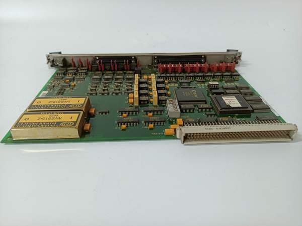
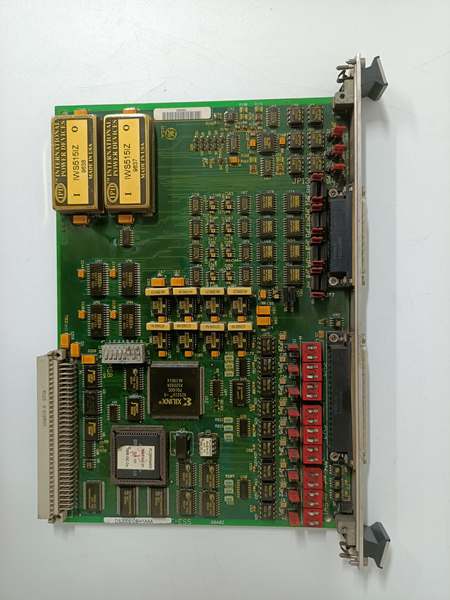
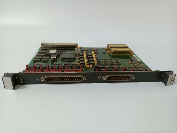
The DS200TBCAG1AAA (Group 1, Revision AAA) is the turbine control terminal board for the Mark V control system. This board provides field wiring termination and signal interface capabilities for connecting diverse field devices to the control system. The revision AAA design represents the initial implementation of this terminal board type, establishing the fundamental architecture for turbine control field device connections. The board features multiple terminal blocks for field wiring termination, providing connection points for digital inputs (limit switches, position switches), analog inputs (pressure transmitters, temperature sensors), and digital outputs (control relays, indicator lamps). Signal conditioning circuitry filters and prepares input signals for processing by the control system, while galvanic isolation protects sensitive control electronics from harsh electrical environments. The Group 1 configuration provides specific I/O channel arrangements optimized for general-purpose turbine control applications.
Signal flow:
- Field devices connect to TBCA terminal blocks (digital inputs, analog inputs, digital outputs)
DS200SIOBH1AAA
- Digital input signals (limit switches, position switches) route through input conditioning circuitry
- Input filtering circuitry removes noise and debounces contact signals
- Configurable pull-up/pull-down resistors set input voltage levels
- Conditioned digital input signals route to R> processor for status monitoring
- Analog input signals (pressure transmitters, temperature sensors) route through analog conditioning
- Analog signal conditioning amplifies and filters analog inputs
- Galvanic isolation protects control system from field transients
- Conditioned analog signals route to R> processor for process variable monitoring
- R> processor issues digital output commands for field device control
- Output signals route through output conditioning circuitry
- Digital outputs drive external relays or indicator lamps
- LED indicators display channel status and fault conditions
- Group 1 configuration provides specific I/O channel arrangements
- Board operates in control core with R> processor redundancy
Field Service Pitfalls: What Rookies Get Wrong
Failing to document terminal connections causes extended downtimeNot mapping wire positions before removal. I’ve seen technicians pulling all field wires without marking terminal IDs, then spending hours tracing connections during replacement.
- Field Rule: Always document terminal connections before removal. Use terminal IDs to mark each wire connection. Photograph the board with all wires attached. Create tags for each terminal connection. Map out all terminal block connections. Never rely on memory—this board has too many connections. Document both digital and analog terminal assignments.
Mixing up digital input and output terminals causes control failuresConfusing input and output connections. I’ve seen technicians connecting limit switches to output terminals and relays to input terminals, causing complete control failure.
- Field Rule: Clearly identify digital inputs and outputs. Digital inputs are for limit switches, position switches, status contacts. Digital outputs are for relays, indicator lamps, control devices. Label all digital signal wires clearly. Verify connections with wiring diagrams. Test input response by activating switches. Never mix up inputs and outputs—reverse connections prevent proper control.
Improper analog input wiring causes reading errorsIncorrect analog sensor connections. I’ve seen technicians wiring analog sensors incorrectly, causing pressure or temperature reading errors or sensor damage.
- Field Rule: Verify analog input wiring is correct. Analog inputs may be voltage (0-10 V) or current (4-20 mA). Check sensor output type matches terminal requirements. Verify sensor power connections (if powered from TBCA). Test analog input readings with known process conditions. Never guess at analog wiring—incorrect connections cause reading errors or sensor damage.
Overlooking pull-up/pull-down configuration causes input erratic behaviorNot setting input pull-up/pull-down resistors correctly. I’ve seen technicians leaving pull-ups/pull-downs in wrong state, causing digital inputs to read erratically.
- Field Rule: Verify pull-up/pull-down resistor configuration matches application. Dry contact inputs typically require pull-up resistors. Sourcing inputs may require pull-down resistors. Check original board jumper or switch settings for pull-up/pull-down configuration. Document settings before removal. Never assume pull-up/pull-down is correct—verify configuration matches field device type.
Neglecting galvanic isolation causes ground loop issuesCompromising isolation barriers. I’ve seen technicians damaging isolation components or creating unintended connections, causing ground loops and erratic signals.
- Field Rule: Verify galvanic isolation is intact. Check isolation resistance between field side and control side. Measure isolation voltage rating—ensure it matches system requirements. Confirm no unintended connections exist between isolated sides. Never compromise isolation barriers—ground loops cause erratic operation.
Confusing TBCA with other terminal board types causes installation errorsMixing up TBCA and other Mark V terminal boards. I’ve seen technicians replacing TBCA with PTBA or other terminal boards, causing incompatible interfaces and connection failures.
- Field Rule: Clearly identify TBCA vs. other terminal boards. TBCA is Turbine Control Terminal Board—for general turbine control I/O. PTBA is Protective Terminal Board—for protection signals. Check board label for “TBCA” designation. Never assume all terminal boards are identical—TBCA provides specific I/O for turbine control.
Skipping AAA revision compatibility verification causes installation failuresInstalling revision AAA without checking compatibility. I’ve seen technicians replacing later TBCA revisions with revision AAA boards, causing compatibility issues with system configuration.
- Field Rule: Verify revision AAA compatibility before installation. Revision AAA may lack features required by current system configuration. Check if system requires later revision features. Compare original board revision with replacement board. Consult GEH-6212 manual for revision compatibility. Never assume revision AAA matches later revisions—verify compatibility first.
Forgetting to verify signal integrity after installation causes latent faultsNot testing signals after board replacement. I’ve seen technicians installing boards without comprehensive signal testing, discovering issues only during turbine startup.
- Field Rule: Perform complete signal verification after TBCA installation. Test all digital inputs by activating switches. Verify digital output operation with test commands. Check analog input readings against known process values. Use Mark V diagnostic tools to confirm all signals are operational. Never assume board works correctly without verification—test all signal paths.
Commercial Availability & Pricing Note
Please note: The listed price is for reference only and is not binding. Final pricing and terms are subject to negotiation based on current market conditions and availability.


