
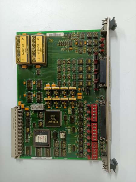
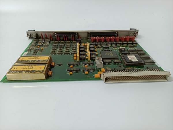
Description
Hard-Numbers: Technical Specifications
- Functional Acronym: SNPA (Servo Non-Position Analog)
- Group Number: G1 (Group 1 variant)
- Revision: AB (Board Revision A, Artwork Revision B)
- Configuration: H1 (H1 non-position analog configuration)
- Core Location: Control Core (R> processor rack) – varies by system configuration
- Analog Inputs: Multiple analog input channels for sensor signals
- Analog Outputs: Multiple analog output channels for servo valve or actuator control
- Signal Types: Voltage and current signals (typically 0-10 V, 4-20 mA, or similar)
- Signal Conditioning: Analog signal conditioning circuitry for noise immunity
- Scaling Adjustment: Potentiometers or software-configurable scaling for analog signals
- Offset Adjustment: Potentiometers or software-configurable offset for analog signals
- Filtering: Analog filtering circuitry for signal noise reduction
- Isolation: Galvanic isolation between control system and field analog signals
- LED Indicators: LED indicators for channel status, fault conditions, and signal presence
- Power Requirements: Typically 24 V DC from control system power supply
- Dimensions: Standard Mark V board form factor (typically 3″ H × 11.5″ W)
- PCB Coating: Normal coating (non-conformal)
- Manual: GEH-6210 (Servo Non-Position Analog Board Manual)

DS200SIOBH1AAA
The Real-World Problem It Solves
The Mark V control system requires analog signal processing and interface capabilities for servo applications that do not involve direct position feedback, such as pressure control loops, flow control loops, temperature compensation circuits, or other analog servo functions. The DS200SNPAH1AB (Servo Non-Position Analog Board – H1 Configuration, Revision AB) provides the analog signal processing and interface capability required for these applications, conditioning analog sensor inputs and generating analog control outputs for servo valves or actuators. Unlike position-based servo boards (such as SIOB or SDCI) that rely on LVDT position feedback, the SNPA board processes continuous analog signals for closed-loop control based on pressure, flow, temperature, or other process variables. The revision AB represents a mature hardware update that may include improved signal conditioning accuracy, enhanced filtering, updated isolation circuits, or functional improvements over earlier revisions. Without this board, non-position servo applications would lack the analog processing capability, requiring separate analog I/O modules or compromising control accuracy.
Where you’ll typically find it:
- Control Core (R> processor rack) – varies by system configuration
- Gas turbine control systems with pressure or flow control loops
- Steam turbine control systems with analog compensation circuits
- Applications requiring analog servo control without position feedback
- Systems with temperature or pressure-based servo functions
- Turbines with non-position servo control requirements using H1 configuration
Bottom line: Analog signal processing interface for non-position servo applications—H1 configuration, revision AB, enabling closed-loop control based on pressure, flow, temperature, or other process variables.
Hardware Architecture & Under-the-Hood Logic
The DS200SNPAH1AB (H1 Configuration, Revision AB) is the servo non-position analog board for the Mark V control system, specifically designed for applications requiring analog signal processing without direct position feedback. This revision AB represents a mature hardware evolution, potentially incorporating improved signal conditioning circuits, enhanced filtering, updated isolation barriers, or artwork modifications based on GE engineering change orders. The H1 configuration differs from other SNPA configurations in analog signal routing, channel assignment, or signal processing characteristics. The board receives analog sensor inputs (pressure transmitters, flow meters, temperature sensors, or other process variables) and processes these signals through conditioning circuitry, filtering, and scaling. Processed signals are used for closed-loop control logic, generating analog control outputs for servo valves or actuators. Unlike position-based servo boards that compare position feedback with command, the SNPA board compares process variable feedback with setpoint and adjusts output to maintain desired process conditions.
Signal flow:
- Analog sensor inputs (pressure, flow, temperature, etc.) connect to SNPA input channels
- Input signal conditioning circuitry filters and amplifies sensor signals
- H1-specific signal processing routes signals through appropriate channels
- Enhanced filtering circuitry (revision AB) reduces signal noise
- Scaling and offset adjustment circuits calibrate signal ranges
- Processed signals route to R> processor for closed-loop control logic
- R> processor issues control command based on process variable feedback
- Control command processed through SNPA output conditioning circuitry
- Analog output signals generated for servo valve or actuator control
- Output signals drive servo valves or actuators to adjust process conditions
- Galvanic isolation protects control system from field analog transients
- LED indicators display channel status, fault conditions, and signal presence
- H1 configuration provides specialized analog signal processing architecture
- Board operates in control core with R> processor redundancy
- No position feedback required—control based on process variables only
DS200SIOBH1AAA
Field Service Pitfalls: What Rookies Get Wrong
Confusing SNPA with position-based servo boards causes installation errorsMixing up SNPA and SIOB/SDCI boards. I’ve seen technicians replacing SNPA with position-based servo boards, causing incorrect signal processing and control failures.
- Field Rule: Clearly identify SNPA vs. position-based servo boards. SNPA is Servo Non-Position Analog—processes analog process variables. SIOB/SDCI are position-based servo boards—use LVDT position feedback. Check board label for “SNPA” designation. Never assume all servo boards are identical—SNPA handles analog process signals, not position feedback.
Overlooking H1 configuration requirements causes signal routing errorsNot understanding H1-specific characteristics. I’ve seen technicians treating H1 configuration like standard analog, causing signal routing issues.
- Field Rule: Understand H1 configuration has unique analog signal characteristics. H1 may use different channel assignments or signal ranges. Analog filtering may differ from standard configuration. Check H1-specific calibration procedures. Never assume H1 matches standard analog—learn H1-specific requirements.
Improper analog signal calibration causes control inaccuracyIncorrect scaling or zero adjustment. I’ve seen technicians not calibrating analog inputs/outputs properly, causing process control deviations from setpoint.
- Field Rule: Always calibrate analog signals after SNPA replacement. Verify input scaling matches sensor output range. Check output scaling matches servo valve or actuator requirements. Adjust scaling and offset potentiometers if required. Test control accuracy across full range. Never assume analog calibration is correct—calibrate after every SNPA change.
Mixing up analog input and output connections causes control failureConfusing analog inputs and outputs. I’ve seen technicians connecting analog sensors to output terminals and vice versa, causing complete control failure.
- Field Rule: Clearly identify analog inputs and outputs. Analog inputs are for sensor signals (pressure, flow, temperature). Analog outputs are for servo valve or actuator control. Label all analog signal wires clearly. Verify connections with wiring diagrams. Test input signals with multimeter—should vary with process conditions. Never mix up inputs and outputs—reverse connections prevent proper control.
Neglecting analog signal filtering causes noise-induced instabilityNot verifying filtering circuitry. I’ve seen technicians causing signal noise by bypassing or damaging filtering components, causing control instability.
- Field Rule: Verify analog signal filtering is intact. Check filtering components (capacitors, inductors) are present and functional. Measure signal-to-noise ratio with oscilloscope if available. Ensure proper grounding for analog signals—ground loops cause noise. Never compromise filtering circuitry—noise causes erratic control behavior.
Skipping AB revision compatibility verification causes installation failuresInstalling revision AB without checking compatibility. I’ve seen technicians replacing earlier SNPA revisions with revision AB boards without verifying compatibility, leading to configuration errors or signal processing failures.
- Field Rule: Verify revision AB compatibility before installation. Revision AB may have different jumper positions, connector assignments, or analog ranges. Compare original board revision with replacement board. Consult GEH-6210 manual for revision compatibility matrix. Check for any engineering change notices (ECNs) applying to revision AB. Document any configuration differences between revisions. Never assume revision AB is drop-in compatible—verify AB-specific requirements.
Forgetting to verify galvanic isolation causes ground loop issuesNot checking isolation integrity. I’ve seen technicians compromising isolation barriers, causing ground loops and erratic analog signals.
- Field Rule: Verify galvanic isolation is intact. Check isolation resistance between control side and field side. Measure isolation voltage rating—ensure it matches system requirements. Confirm no unintended connections exist between isolated sides. Never compromise isolation barriers—ground loops cause erratic analog signals and control instability.
Overlooking AB-specific diagnostic capabilities causes missed fault informationNot utilizing AB-specific diagnostic features. I’ve seen technicians installing revision AB boards but not understanding enhanced diagnostic features, failing to leverage improved capabilities.
- Field Rule: Learn revision AB-specific diagnostic enhancements. AB may have improved LED indication or diagnostic capabilities. Check for additional channel status indicators. Use enhanced diagnostic features for fault identification. Document AB-specific features compared to earlier revisions. Never assume AB is just a minor update—utilize AB enhancements.
Commercial Availability & Pricing Note
Please note: The listed price is for reference only and is not binding. Final pricing and terms are subject to negotiation based on current market conditions and availability.


