
Description
Hard-Numbers: Technical Specifications
- Functional Acronym: SLCC (Servo Loop Control Card)
- Group Number: G3 (Group 3 variant)
- Revision: CC (Board Revision C, Artwork Revision C)
- Core Location: Control Core (R> processor rack) – varies by system configuration
- Servo Loops: Multiple servo loop control channels (Group 3-specific configuration)
- Control Algorithm: Group 3-specific servo loop algorithms (PID, lead-lag, or specialized control)
- Command Input: Digital command input from R> processor
- Feedback Processing: Enhanced feedback signal processing for Group 3 applications
- Output Generation: Servo drive signal generation for servo valve control
- Gain Adjustment: Software-configurable gain parameters via R> processor
- Offset Adjustment: Software-configurable offset parameters via R> processor
- Trip Function: Integrated trip logic for emergency actuator shutdown
- Isolation: Galvanic isolation between control system and servo equipment
- LED Indicators: LED indicators for servo status, fault conditions, and loop status
- Power Requirements: Typically 24 V DC or 125 V DC from control system power supply
- Dimensions: Standard Mark V board form factor (typically 3″ H × 11.5″ W)
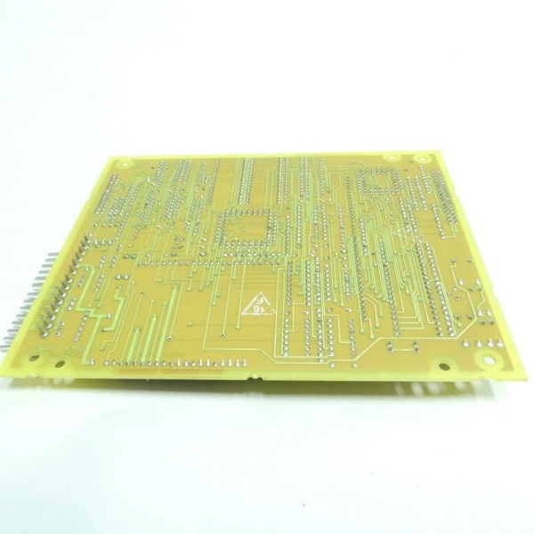
- PCB Coating: Normal coating (non-conformal)
- Manual: GEH-6207 (Servo Loop Control Board Manual)

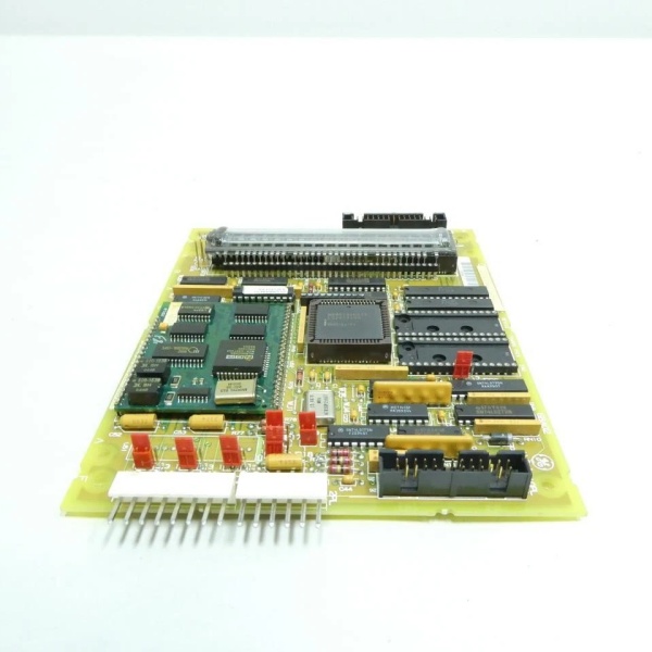
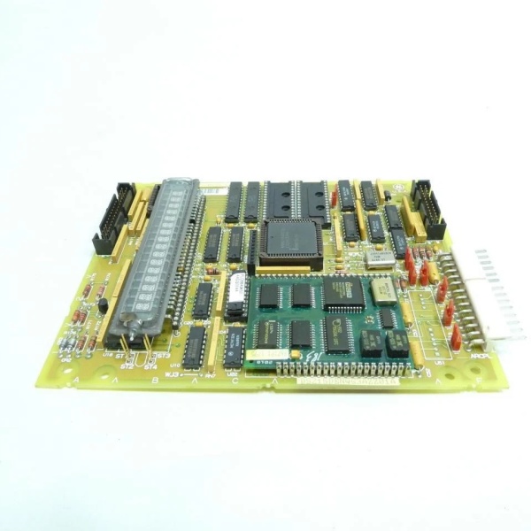
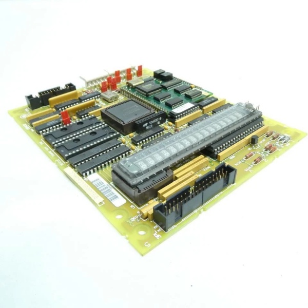
GE DS200SLCCG3ACC
The Real-World Problem It Solves
The Mark V control system requires dedicated servo loop processing for implementing precise closed-loop control algorithms beyond what standard servo interface boards can provide. The DS200SLCCG3ACC (Servo Loop Control Board – Group 3, Revision CC) provides advanced servo loop control logic and processing capability for Group 3 applications that require specialized control algorithms or enhanced feedback processing. This board implements servo loop algorithms (PID, lead-lag compensation, or specialized control schemes) that execute faster or more accurately than the main R> processor, enabling more precise actuator positioning and faster response to command changes. The revision CC represents a mature hardware update that may include improved algorithm execution speed, enhanced feedback processing accuracy, or additional diagnostic capabilities over earlier revisions. Without this board, Group 3 servo control applications would lack the processing power required for advanced control algorithms, leading to suboptimal actuator performance or response time limitations.
Where you’ll typically find it:
- Control Core (R> processor rack) – varies by system configuration
- Gas turbine control systems requiring Group 3 servo loop algorithms
- Steam turbine control systems with advanced servo control requirements
- Applications requiring faster servo loop response than standard interface boards
- Systems with specialized control algorithm requirements
- Turbines with high-performance servo control applications
Bottom line: Advanced servo loop processing for Group 3 applications—revision CC configuration, implementing precise closed-loop control algorithms for optimal actuator performance and response time.
Hardware Architecture & Under-the-Hood Logic
The DS200SLCCG3ACC (Group 3, Revision CC) is the servo loop control board for the Mark V control system, specifically designed for applications requiring Group 3 servo loop processing. This revision CC represents a mature hardware evolution, potentially incorporating improved algorithm execution circuits, enhanced feedback processing, updated processor components, or artwork modifications based on GE engineering change orders. The Group 3 configuration differs from other SLCC groups in control algorithm implementation, feedback processing characteristics, or servo loop architecture. The board receives digital position commands and control parameters from the R> processor and executes servo loop control algorithms to generate precise servo drive signals. Position feedback from servo interface boards (such as SIOB or SDCI) is processed through Group 3-specific algorithms to calculate position error and generate corrective drive signals. The revision CC design may include improved processor performance, enhanced algorithm accuracy, or additional diagnostic capabilities compared to earlier revisions.
Signal flow:
- R> processor issues digital position command and control parameters to SLCC (Group 3)
- Group 3 servo loop algorithm processes command and generates drive signal
- Servo drive signal routes to servo interface board (SIOB/SDCI) for valve control
- Servo interface board drives servo valve and actuator
- Actuator position changes are detected by position feedback device
- Position feedback returns through servo interface board to SLCC
- Group 3 feedback processing algorithms extract position information
- Servo loop calculates position error using Group 3-specific algorithms
- Algorithm generates corrective drive signal to minimize position error
- Software-configurable gain and offset parameters are applied via R> processor
- Integrated trip logic provides emergency actuator shutdown
- Galvanic isolation protects control system from servo equipment transients
- LED indicators display servo status, fault conditions, and loop status
- Group 3 configuration provides specialized control algorithm architecture
- Board operates in control core with R> processor redundancy
GE DS200SLCCG3ACC
Field Service Pitfalls: What Rookies Get Wrong
Confusing SLCC with servo interface boards causes installation errorsMixing up SLCC and SIOB/SDCI boards. I’ve seen technicians replacing SLCC with servo interface boards, causing lack of loop processing and control failures.
- Field Rule: Clearly identify SLCC vs. servo interface boards. SLCC is Servo Loop Control Card—executes control algorithms. SIOB/SDCI are servo interface boards—provide physical interface to servo valves. Check board label for “SLCC” designation. Never assume all servo boards are identical—SLCC provides loop processing, interface boards provide physical connection.
Assuming Group 3 algorithms match other groups causes control instabilityNot understanding Group 3-specific characteristics. I’ve seen technicians expecting Group 3 to behave like other groups, causing actuator response issues.
- Field Rule: Understand Group 3 may have different control algorithm characteristics. Group 3 may use specialized PID parameters or lead-lag compensation. Servo loop response times may differ from other groups. Check Group 3-specific tuning procedures. Never assume Group 3 matches other groups—learn Group 3-specific requirements.
Failing to verify CC revision software compatibility causes configuration errorsInstalling revision CC without checking software compatibility. I’ve seen technicians replacing earlier SLCC revisions with revision CC boards without verifying software compatibility, leading to parameter mismatch or algorithm errors.
- Field Rule: Verify revision CC software compatibility before installation. Revision CC may require updated R> processor software or different parameter formats. Check R> processor software version compatibility. Verify control algorithms in software match revision CC capabilities. Consult GEH-6207 manual for software compatibility requirements. Never assume hardware compatibility equals software compatibility—verify both.
Overlooking software-configurable gain/offset causes tuning issuesNot understanding software parameter requirements. I’ve seen technicians looking for hardware gain potentiometers on SLCC, not realizing Group 3 uses software configuration.
- Field Rule: Understand SLCC gain and offset are software-configurable via R> processor. Group 3 SLCC typically has no hardware gain/offset potentiometers. Gain and offset parameters must be configured in R> processor software. Document software parameter values before board replacement. Never look for hardware potentiometers on SLCC—Group 3 uses software configuration.
Forgetting to verify Group 3 jumper settings causes configuration errorsMissing Group 3 configuration jumpers. I’ve seen technicians setting jumpers based on other group knowledge, causing incorrect Group 3 operation.
- Field Rule: Verify Group 3-specific jumper settings are correct. Group 3 may have different jumper positions or configuration options. Document original jumper positions before removal. Compare new board jumper configuration with original. Consult GEH-6207 manual for Group 3 jumper descriptions. Never assume other group jumpers match Group 3—verify Group 3-specific settings.
Skipping CC compatibility verification causes installation failuresInstalling revision CC without checking compatibility. I’ve seen technicians replacing earlier SLCC revisions with revision CC boards without verifying compatibility, leading to configuration errors or processing failures.
- Field Rule: Verify revision CC compatibility before installation. Revision CC may have different jumper positions, connector assignments, or algorithm capabilities. Compare original board revision with replacement board. Consult GEH-6207 manual for revision compatibility matrix. Check for any engineering change notices (ECNs) applying to revision CC. Document any configuration differences between revisions. Never assume revision CC is drop-in compatible—verify CC-specific requirements.
Misunderstanding SLCC-SIOB/SDCI relationship causes wiring errorsConfusing signal flow between SLCC and interface boards. I’ve seen technicians misunderstanding how SLCC connects to servo interface boards, causing incorrect wiring.
- Field Rule: Understand signal flow between SLCC and servo interface boards. SLCC processes servo loop algorithms and generates drive signals. Drive signals route to SIOB/SDCI interface boards. SIOB/SDCI provide physical interface to servo valves. Position feedback from interface boards returns to SLCC for processing. Verify correct ribbon cable connections between SLCC and interface boards. Never bypass interface boards—SLCC requires interface board for physical connection.
Overlooking CC-specific diagnostic LEDs causes missed fault informationNot understanding CC LED indication patterns. I’ve seen technicians ignoring additional LED indicators on revision CC, missing valuable diagnostic information.
- Field Rule: Learn revision CC-specific LED indication patterns. CC may have additional LED indicators or different flash patterns. Understand what each LED indicates (algorithm status, fault type, loop status). Use LED information for fault diagnosis. Never assume LED behavior matches earlier revisions—learn CC-specific LED patterns.
Commercial Availability & Pricing Note
Please note: The listed price is for reference only and is not binding. Final pricing and terms are subject to negotiation based on current market conditions and availability.


