
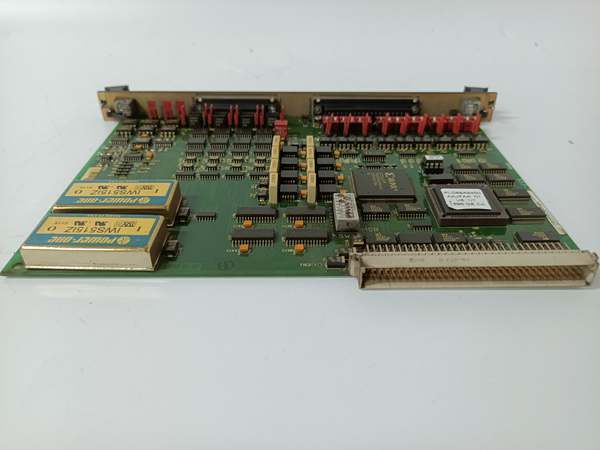
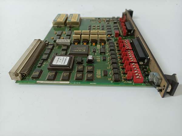
Description
Hard-Numbers: Technical Specifications
- Functional Acronym: SIOB (Servo Interface Output Board)
- Group Number: G1 (Group 1 variant)
- Revision: BA (Board Revision B, Artwork Revision A)
- Configuration: H1 (H1 servo interface configuration)
- Core Location: Control Core (R> processor rack) – varies by system configuration
- Servo Interfaces: H1-specific servo control interfaces
- Command Output: Analog and/or digital command outputs to servo controllers
- Feedback Input: Multiple feedback input channels (LVDT, resolver, or encoder feedback)
- Position Feedback: LVDT (Linear Variable Differential Transformer) inputs for position sensing
- Signal Conditioning: H1-specific signal conditioning for optimized performance
- Gain/Offset Adjustment: Potentiometers for servo loop tuning
- Trip Function: Integrated trip output for emergency actuator shutdown
- Isolation: Galvanic isolation between control system ground and servo equipment ground
- LED Indicators: LED indicators for servo status, fault conditions, and feedback status
- Power Requirements: Typically 24 V DC or 125 V DC from control system power supply
- Dimensions: Standard Mark V board form factor (typically 3″ H × 11.5″ W)
- PCB Coating: Normal coating (non-conformal)
- Manual: GEH-6203 (Servo Interface Board Manual)

DS200SIOBH1ABA
The Real-World Problem It Solves
The Mark V control system requires specialized servo interface configurations for applications with unique actuator arrangements or specific H1 architecture requirements. The DS200SIOBH1ABA (Servo Interface Board – H1 Configuration, Revision BA) provides H1-specific servo interface options that differ from other servo configurations in signal processing characteristics, feedback channel configuration, or I/O capacity. This board enables closed-loop servo control for specific fuel valve types, specialized steam control arrangements, or custom position control applications that require the H1 architecture. The revision BA represents a mature hardware update that may include improved signal conditioning accuracy, enhanced feedback processing, updated isolation circuits, or functional improvements over earlier revisions such as revision A. Without this board, H1-configured servo control applications would lack the proper interface, leading to suboptimal actuator performance or incompatible system configurations.
Where you’ll typically find it:
- Control Core (R> processor rack) – varies by system configuration
- Gas turbine control systems with H1-configured fuel valves
- Steam turbine control systems with H1 valve arrangements
- Applications requiring H1 servo interface architecture
- Systems with custom position control requirements
- Turbines with specific actuator configurations requiring H1 interface
Bottom line: Specialized H1 servo interface for unique actuator control requirements—revision BA configuration, providing enhanced signal processing and feedback capabilities for H1 architecture applications.
Hardware Architecture & Under-the-Hood Logic
The DS200SIOBH1ABA (H1 Configuration, Revision BA) is the servo interface board for the Mark V control system, specifically designed for applications requiring H1 servo architecture. This revision BA represents a mature hardware evolution, potentially incorporating improved signal conditioning circuits, enhanced feedback processing, updated isolation barriers, or artwork modifications based on GE engineering change orders. The H1 configuration differs from other servo configurations in signal processing characteristics, feedback channel configuration, I/O capacity, or servo loop architecture. The board receives digital position commands from the R> processor and converts these commands into servo-compatible analog or digital command signals. Position feedback from LVDTs, resolvers, or encoders is conditioned and processed through H1-specific signal paths to provide accurate position information for closed-loop control. The revision BA design may include improved LVDT excitation stability, enhanced analog output accuracy, or additional diagnostic capabilities compared to earlier revisions.
Signal flow:
- R> processor issues digital position command to SIOB (H1 configuration, revision BA)
- H1 command conversion circuitry generates servo-compatible output
- Servo controller receives command signal and drives actuator accordingly
- Actuator position changes are detected by position feedback device
- LVDT excitation circuitry provides AC excitation to LVDT primary
- H1-specific feedback conditioning processes feedback signals
- Enhanced feedback processing circuitry (revision BA) extracts position information
- Position feedback returns to servo loop for error calculation
- Servo loop calculates position error and adjusts servo output accordingly
- Gain and offset potentiometers allow H1-specific servo loop tuning
- Integrated trip function provides emergency actuator shutdown
- Galvanic isolation separates control system ground from servo equipment ground
- LED indicators display servo status, fault conditions, and feedback status
- H1 configuration provides specialized signal processing architecture
- Board operates in control core with R> processor redundancy
DS200SIOBH1ABA
Field Service Pitfalls: What Rookies Get Wrong
Assuming revision BA behaves identically to earlier revisions causes diagnosis confusionNot understanding BA-specific improvements. I’ve seen technicians expecting revision BA to behave exactly like revision A or AAA, causing confusion when troubleshooting signal issues.
- Field Rule: Understand revision BA may have different operational characteristics. Signal conditioning may be enhanced compared to earlier revisions. LVDT excitation stability may be improved. Feedback processing accuracy may be different. LED indication patterns may differ. Consult revision BA-specific documentation for operational differences. Never assume BA behavior matches earlier revisions—learn BA-specific characteristics.
Failing to verify BA-enhanced feedback processing causes calibration errorsNot validating improved feedback signal accuracy. I’ve seen technicians installing revision BA boards but not verifying improved feedback processing characteristics, causing calibration errors or position inaccuracy.
- Field Rule: Verify revision BA feedback processing characteristics after installation. Test feedback signal accuracy with known displacements. Check feedback stability across full range. Compare feedback readings with earlier revision if available. Verify feedback matches actuator actual position. Calibrate feedback scaling if adjustable. Never assume feedback processing is unchanged—BA may have improved accuracy or different characteristics.
Confusing SIOB BA with SIOB A, AAA, or SI0B boards causes installation errorsMixing up SIOB revision levels and board types. I’ve seen technicians replacing SIOB BA with SIOB A, SIOB AAA, or SI0B boards, causing incompatible interfaces and control failures.
- Field Rule: Clearly identify board type and revision. SIOB BA is Servo Interface Output Board revision BA—different from SIOB A, SIOB AAA, and SI0B. Check board label for “SIOB” and “BA” designations. Compare original board type and revision with replacement board. Consult GEH-6203 manual for specific configuration. Never assume similar model names are identical—verify both board type and revision match application requirements.
Improper LVDT calibration despite BA improvements causes position errorIncorrect LVDT scaling or zero adjustment. I’ve seen technicians assuming BA enhancements compensate for poor LVDT calibration, causing actuators to drift or fail to reach commanded position.
- Field Rule: Always calibrate LVDT feedback after SIOB replacement, even with BA enhancements. Verify LVDT zero position corresponds to actual actuator zero. Check LVDT full-scale position matches actuator full travel. Adjust LVDT scaling potentiometers if required. Test position accuracy across entire range. Never assume BA improvements eliminate need for calibration—calibrate after every SIOB change.
Forgetting to verify H1-specific jumper settings causes configuration errorsMissing H1 configuration jumpers. I’ve seen technicians setting jumpers based on standard servo knowledge, causing incorrect H1 operation.
- Field Rule: Verify H1-specific jumper settings are correct. H1 configuration may have different jumper positions or configuration options. Document original jumper positions before removal. Compare new board jumper configuration with original. Consult GEH-6203 manual for H1 jumper descriptions. Never assume standard servo jumpers match H1—verify H1-specific settings.
Skipping BA compatibility verification causes installation failuresInstalling revision BA without checking compatibility. I’ve seen technicians replacing earlier SIOB revisions with revision BA boards without verifying compatibility, leading to configuration errors or interface failures.
- Field Rule: Verify revision BA compatibility before installation. Revision BA may have different jumper positions, connector assignments, or component values. Compare original board revision with replacement board. Consult GEH-6203 manual for revision compatibility matrix. Check for any engineering change notices (ECNs) applying to revision BA. Document any configuration differences between revisions. Never assume revision BA is drop-in compatible—verify BA-specific requirements.
Overlooking BA-specific diagnostic LEDs causes missed fault informationNot understanding BA LED indication patterns. I’ve seen technicians ignoring additional LED indicators on revision BA, missing valuable diagnostic information.
- Field Rule: Learn revision BA-specific LED indication patterns. BA may have additional LED indicators or different flash patterns. Understand what each LED indicates (status, fault, feedback validity, trip status). Use LED information for fault diagnosis. Never assume LED behavior matches earlier revisions—learn BA-specific LED patterns.
Improper servo loop tuning despite BA enhancements causes control instabilityMisadjusting gain and offset potentiometers. I’ve seen technicians not understanding BA-enhanced processing, setting gain/offset incorrectly, causing oscillation or sluggish response.
- Field Rule: Adjust H1 servo loop gain and offset carefully, considering BA enhancements. BA-enhanced feedback processing may require different gain settings than earlier revisions. Start with original board settings, then fine-tune if needed. Monitor actuator response during adjustment. Document final potentiometer settings. Never assume gain/offset settings transfer directly—BA may require different tuning.
Commercial Availability & Pricing Note
Please note: The listed price is for reference reference only and is not binding. Final pricing and terms are subject to negotiation based on current market conditions and availability.


