
Description
Product Introduction
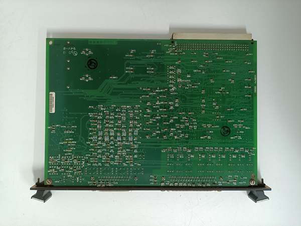
The is a VME-based I/O control board central to the Mark V turbine control system (often functionally referred to as TCQA – Signal Conditioning). It occupies a full slot in the <R1>, <R2>, or <R3>I/O cores, interfacing directly with terminal boards (like STCA, TCQC) via a 40-pin ribbon cable.
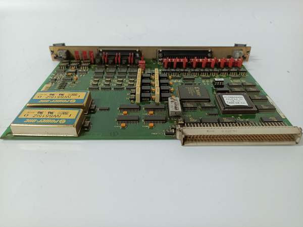
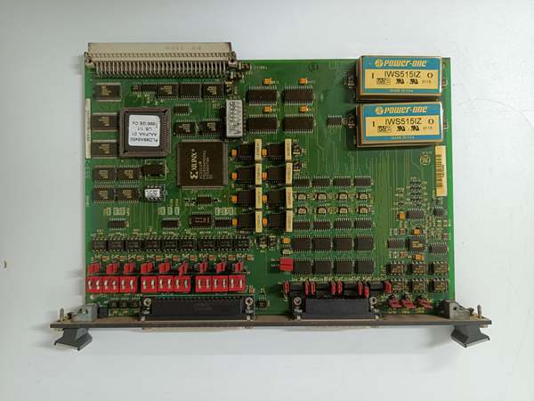
Its primary role is signal scaling and conditioning. It processes complex field data—including LVDT position feedback, thermocouples, and 4-20mA loops—converting them into digital words for the VME processor. The “ABA” suffix indicates a specific hardware revision with conformal coating (B-rev) for moisture/dust resistance and updated artwork (A-rev), making it suitable for harsh turbine environments. Configuration is highly hardware-dependent, utilizing 20 jumpers and 3 blocks of DIP switches (18 switches total) to set voltage ranges, attenuation, and logic levels .
DS200SIOBH1ABA
Key Technical Specifications
- System Role: SIOB (Signal I/O Bridge / TCQA)
- Bus Interface: VMEbus (Occupies 1 Full Slot, P1 Connector)
- Logic Voltage: 5 V DC (±5%, drawn from Backplane)
- Configuration:
- 20 Configurable Jumpers (Set current ranges, attenuation)
- 3 Switch Blocks (18 DIP Switches total for logic/addressing)
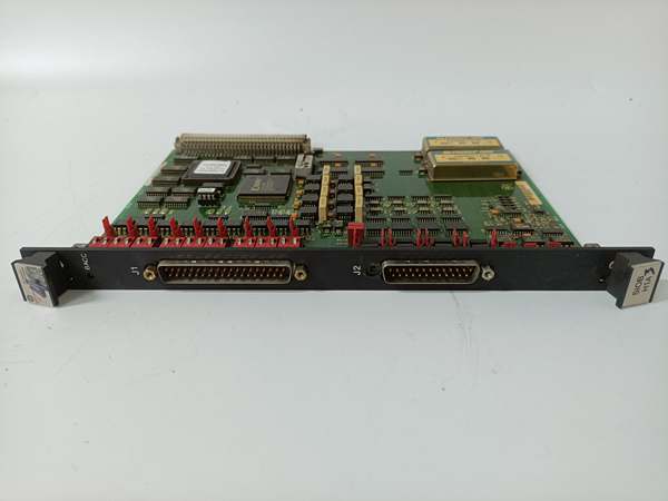
- Field Interface: 1x 40-pin IDC Connector (To Terminal Board)
- Indicators: 1x LED (Indicates VME Bus Access / Health)
- Signal Types: LVDT, Thermocouple, 4-20mA, Servo Drive, Discrete
- Coating: Conformal Coated (ABA Revision)
- Temp Range: -20 °C to +65 °C (Operational, typical)
- Architecture: Group 1 (G1) / Stand I/O
Quality Control Process (Engineer’s Perspective)
- Incoming Verification: Match serial to docs. Inspect the 96-pin VME fingers (P1) for carbon scoring (sign of past backplane arcs). Check the 40-pin IDC header for cracked plastic or bent pins.
- Configuration Audit: Photograph the jumper and DIP switch positions before testing. This is the “DNA” of the board. Any mismatch here will cause signal scaling errors (e.g., LVDT reading 50% when valve is 0%).
- Live Bus Test: Seat in a Mark V core simulator with 5V DC. Verify the LED illuminates steadily (indicates VME arbiter access). Scope the 40-pin lines for clean data transitions without ringing.
- Signal Simulation: Inject a 4-20mA signal into a simulated loop. Verify the onboard op-amps scale it correctly based on jumper settings (e.g., 1:1 vs 1:5 attenuation). Noise floor should be < 10mV.
- Final QC & Packaging: Clean VME fingers with isopropanol. Bag in rigid ESD foam (VME cards are heavy). Label “QC Passed – Config Logged” with the date.
Replacement Pitfall Guide
❗ Jumper/Switch Cloning (The #1 Rule): The is not plug-and-play. You must set the 20 jumpers and 18 DIP switches on the newboard to exactly match the old/failed board.
- Example:If Jumper JP1 was set for “20mA Span” on the old unit and you leave the new one at “4mA Default,” your fuel valve calibration will be 500% off, potentially causing an overspeed trip. Take a photo of the old board before removing it.
❗ SIOB vs Other SIOs: This is an SIOB (General Signal). Do not confuse it with SIOS (Servo) or SIOT (Trip) boards. While they look identical physically, forcing an SIOB into a slot addressed for SIOS will result in “Processor Mismatch” or incorrect servo drive voltages.
❗ VME Seating & Bent Pins: The P1 connector is 96 pins. “Half-seating” causes intermittent communication (Board drops off VME bus randomly). Apply even pressure. Visually inspect the backplane slots in the rack—if a previous tech pried out the old board with a screwdriver, the rack’spins might be bent, not the board’s.
❗ Coating Compatibility: This is an “ABA” (Coated) unit. If replacing a bare “A” unit in a high-humidity area (e.g., steam turbine bypass), the coated version is superior. However, if the site’s ToolboxST configuration has specific checksum expectations for hardware revisions, a mismatch might flag a “Config Changed” warning (usually advisory, but check with lead engineer).
❗ 40-Pin Ribbon Stress: The cable to the terminal board (STCA/etc.) exerts leverage. Ensure the 40-pin header is soldered securely; cracked solder joints here cause “Loss of Input” faults that appear intermittently.
Keep these in mind and you’ll cut 90% of rework time.
DS200SIOBH1ABA
Compatibility Matrix & Benchmarks
- → GE DS200SIOBH1A: Direct— “ABA” is a coated/sub-revision of H1A. Functionally identical if jumpers are cloned. The “B” artwork may have improved noise filtering.
- → Mark V I/O Core (R1/R2/R3): Direct— Slides into standard VME slots addressed for SIOB/TCQA.
- → Mark VIe (IS200 Series): Incompatible— Mark VIe uses different backplane architecture (e.g., Profibus or Ethernet-based I/O). The is electrically and mechanically incompatible with VIe racks.
- Signal Accuracy: Dependent on Jumper Config (16-bit equivalent scaling)
- Bus Speed: VMEbus Standard (~2 MB/s typical throughput)
- Isolation: Galvanic separation between 5V logic and 24V/Field side (via optos on terminal board)


