
Description
Product Introduction
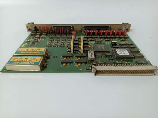
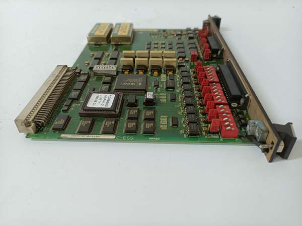
The is a VME Stand I/O board central to the Mark V turbine control system, typically occupying a slot in the I/O cores (<R1>, <R2>, <R3>). Within the Mark V architecture, this board is frequently designated as TCQA (Signal Conditioning & Scaling).
Its primary role is bridging field-terminal boards (like STCA for analog/Servo and TCQC for thermocouples) with the VME processor. It handles complex analog signal conditioning, including LVDT position feedback, Thermocouple temperature inputs, and standard 4-20mA process loops. The “ABA” suffix denotes three layers of revision (A-primary, B-secondary, A-artwork) and confirms the board features conformal coating for moisture/dust resistance in harsh turbine environments. Configuration is heavily hardware-dependent, utilizing 20 jumpers and 3 blocks of DIP switches (18 switches total) to set scaling ranges and signal logic .
GE DS200SIOBH1ABA
Key Technical Specifications
- System Role: SIOB (Signal I/O Bridge) / TCQA (Conditioning)
- Bus Interface: VMEbus (Occupies 1 Full Slot, P1 Connector)
- Logic Voltage: +5 V DC (±5%, sourced from Backplane)
- Configuration:
- 20 Configurable Jumpers (Set current ranges, attenuation, logic)
- 3 Switch Blocks (18 DIP Switches total for addressing/scaling)
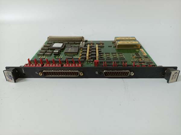
- Field Interface: 1x 40-pin IDC Connector (To Terminal Board)
- Indicators: 1x LED (Illuminates during VME Bus Access / Activity)
- Signal Types: LVDT, Thermocouple, 4-20mA, Servo Drive, Discrete
- Coating: Conformal Coated (ABA Revision)
- Temp Range: -20 °C to +60 °C (Operational, typical)
- Architecture: Group 1 (G1) / Stand I/O
Quality Control Process (Engineer’s Perspective)
- Incoming Verification: Match serial to documentation. Inspect the 96-pin VME fingers (P1) for carbon tracking (sign of past surges) and the 40-pin IDC header for cracked plastic or bent pins.
- Configuration Audit (Critical): Photograph all 20 jumper positions and 18 DIP switch settings on the old/failed board before removal. This is the “calibration DNA” of the card. Any mismatch will cause incorrect scaling (e.g., a 50% valve signal reading as 0% or 100%).
- Live Bus Test: Seat in a Mark V core simulator with 5V DC. Verify the LED blinks/illuminates during VME access. Scope the 40-pin lines for clean transitions without ringing/noise.
- Signal Simulation: Inject a calibrated 4-20mA signal. Verify the onboard op-amps scale it according to the jumper settings (e.g., 1:1 vs 1:5 attenuation). Noise floor should be <10mV p-p.
- Final QC & Packaging: Clean VME fingers with isopropanol. Bag in rigid ESD foam. Label “QC Passed – Config Logged & Scaled” with the date.
Replacement Pitfall Guide
❗ Jumper/Switch Cloning (Mandatory): This board is not plug-and-play. The relies entirely on its 20 jumpers and 18 DIP switches to define how it interprets sensor data.
- Scenario:If Jumper JP5 was set for “20mA Span” on the old unit and the new one defaults to “4mA”, your fuel valve calibration will be 500% off, risking overspeed or shutdown.
- Action:Photograph the old board’s settings and replicate them exactly on the new board before racking.
❗ SIOB vs SIOS/SIOC: This is an SIOB (General Signal/Conditioning). Do not install it in a slot addressed for SIOS (Servo Output) or SIOC (Carrier). While physically identical, the VME address map differs; forcing SIOB into a SIOS slot causes “Processor Mismatch” and loss of servo control.
❗ VME Seating & Backplane Damage: The P1 connector is 96 pins. “Half-seating” causes intermittent “Bus Error” faults. Visually inspect the rack’s backplane slots too—if a previous tech pried out a stuck board with a screwdriver, the rack’spins might be bent, not the board’s.
❗ Coating & Environment: “ABA” is coated. If replacing a bare “A” unit in a steam/turbine hall, the coated version is superior. However, if the site’s software checksums hardware revisions strictly, a mismatch might flag a “Config Changed” warning (usually advisory, but verify with lead).
❗ 40-Pin Ribbon Stress: The cable to the terminal board (STCA/TCQC) exerts leverage. Ensure the 40-pin header is well-soldered; cracked solder joints here cause “Loss of Input” faults that appear intermittently during turbine vibration.
Keep these in mind and you’ll cut 90% of rework time.
GE DS200SIOBH1ABA
Compatibility Matrix & Benchmarks
- → GE DS200SIOBH1A: Direct— “ABA” is a revised/sub-revision of H1A. Functionally identical if jumpers/switches are cloned. “ABA” offers improved coating/artwork.
- → GE DS200SIOBH1AAA: Different Function— “AAA” is often a Serial I/O (Comm) board. Do not swap “ABA” (Analog/Cond.) with “AAA” (Serial) unless the I/O Core config (
.tcf) defines the slot for both roles. - → Mark V I/O Core (R1/R2/R3): Direct— Slides into standard VME slots addressed for SIOB/TCQA.
- → Mark VIe (IS200 Series): Incompatible— Different backplane architecture (VME vs IONet/Ethernet).
- Signal Accuracy: Dependent on Jumper Config (Equivalent to 12-16 bit scaling)
- Bus Speed: VMEbus Standard (~2 MB/s typical throughput)
- Isolation: Galvanic separation via optos on Terminal Board (Field side)


